OPERATIONS MANUAL Nx8- Dual Composite MUX High-Speed 16-Port TDM Multiplexer 31 August, 2006 FOR TECHNICAL SUPPORT CALL: East Coast Datacom, Inc. 245 Gus Hipp Blvd., STE #3 Rockledge, FL 32955 USA TEL: (800) 240-7948 or (321) 637-9922 FAX: (321) 637-9980 WEB: www.ecdata.com Manufactured by: East Coast Datacom, Inc.
1 Introduction............................................................................................................................. 3 1.1 Network Configurations ..................................................................................................... 3 1.2 Planning ............................................................................................................................ 4 2 Key Functions ...............................................................................
.1.3 4.2 Redundant Power Supply .......................................................................................... 37 Console Operation .......................................................................................................... 37 4.2.1 Console Setup............................................................................................................ 37 4.3 Power-Up Login & Logoff ............................................................................................
SAFETY WARNING Always observe standard safety precautions during installation, operation and maintenance of this product. To avoid the possibility of electrical shock, be sure to disconnect the power cord from the power source before you remove the IEC power fuses or perform any repairs. PROPRIETARY NOTICE The information contained herein is proprietary to East Coast Datacom, Inc.
166119 2 8/31/2006
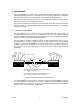
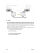
1 Introduction The Nx8-DualMUX is a modular, 16 Port Dual-composite TDM multiplexer for high-speed serial data terminal equipment. It is designed to work in a paired, point-to-point configuration over one or two synchronous composite clear-channel links of up to 128Kbps each. The system may be configured with from 4 to 16 channel ports, operating at rates up to 38.4 Kbps asynchronous, or up to 64Kbps synchronous.
Figure 2 Point-to-point Link as Sub-multiplexer 1.2 Planning The network administrator must determine how the Nx8-DualMUX units will work in the network and understand the applications that will utilize each of the available channels. Some of this work is made easier by the fact that link bandwidth requirements are easily determined by summing the bandwidth needs of each channel port that is planned to be used, and adding the fixed overhead.
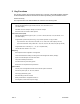
2 Key Functions This section presents the functional operation and concepts of the Nx64-DualMUX. Readers should familiarize themselves with this section before proceeding to the Installation section. Feature Summary The major features of the Nx8-DualMUX are outlined in the following table: Composite Port Interface (DTE) Software-selectable interface types: RS-232, EIA-530, V.35*, RS-422/449*, X.
2.1 Multiplexer Operation The central hardware element of the Nx8-DualMUX is a multiplexer/demultiplexer function through which all end-to-end user and management information flows. The drawing of Figure 3 provides a high-level reference diagram for this function. Other functions such as clock synthesis and synchronization, backup and restoral of channels and links, control paths and programming, and user interfaces are not included. Composite Port I/F Loopback Functions Frame Synch.
2.1.1.1 Timeslots and Channel Rates The number of timeslots assigned to a channel determine the bandwidth of the channel, Since the frame rate is constant, the greater the number of channel bits in the frame, the greater the port rate that can be supported. The basic frame rate is 400 frames-per-second, and each channel bit, or timeslot in the frame provides 400 Hz of bandwidth available for allocation to a channel. This allows port rates that are multiples of this rate to be supported. For example, 19.
20 - (320) bits 1 2 3 Channel "a" allocated = 2400Bps F M1 M2 M3 Da1 Da2 4 5 6 7 8 9 10 Channel "b" allocated = 2400Bps F M1 M2 M3 Da1 Da2 Db1 Db2 Da3 Db3 11 Da3 . . . 12 13 14 15 16 17 18 Da4 Da5 Da6 Da4 Db4 Da5 Db5 Da6 19 20 Db6 F - Framing timeslot M - Management channel timeslot Da, Db - Data channel a or b timeslot Figure 4 – Frame and Super-frame Multiplexing 2.1.
minimizes the duration of the interruption and eliminates the need for the operator to manually enter the sequence of commands. The Nx8-DualMUX has an additional feature that re-allocates channels to new timeslots when the composite link rate is changed by the user. This is particularly important when the composite link rate is decreased, with a corresponding reduction in the size of the timeslot allocation memory.
COMPOSITE DTE to DTE CONNECTION DIAGRAM Rx data latch Internal Oscillator Transmitted TXCE is used to clock out TXD Tx data latch Clock Source RXD RXD RXC RXC TXD TXD TXC TXC TXCE Rx data latch Tx data latch Transmitted TxCE is used to clock out TXD Clock Source TXCE RxC Loop TxCE Enable TxCE Enable Multiplexer 1 Internal-timed DTE Cross-over "null modem" cable connections Loop-timed DTE Multiplexer 2 Figure 5 Composite port cable diagram for DTE-to-DTE connections Other non-symme
For the Nx8-DualMUX, any parameter entry to the composite link rate causes the system to 1) resize the timeslot allocation memory map to the new frame size, 2) re-allocate all channels with non-zero clock rates to fit in the new allocation map, and 3) stores the complete configuration in non-volatile memory.
2.1.7 Channel Port Operation The 16 channel ports may be configured individually according to their various port options. All ports are implemented as DCE interfaces and provide clocking to the attached terminal equipment. Any supported channel rate may be configured on any channel, from 1200 bps to 64Kbps. The only remaining limitation being that the aggregate channel rate of all ports may not exceed the available user bandwidth of the composite link.
In the first and default mode, the DCD signal follows the state of the composite synchronization detector. Thus if SYNC is ON, DCD at the channel port is ON, and OFF if SYNC is OFF. In the second mode, the DCD signal may be configured to respond according to the state of the corresponding channel port RTS input at the far end of the link. This configuration option may be set at either end, or both ends of the channel as needed.
2.2 System Operation 2.2.1 Configuration Management Functions The configuration management functions are those features to which an operator has access for the purpose of installing, and configuring a working end-to-end multiplexer link. Many of these functions are self-explanatory and are thoroughly addressed in Section 4.2-Console Operation. However, certain fundamental aspects of the configuration management process are noteworthy and are discussed in the following sections. 2.2.1.
bandwidth is added to carry the control signal end-to-end. While bandwidth is added in both directions, only the port selected to respond to the RTS from the opposite end of the channel will operate in this mode. If this option is changed while the channel is allocated, there will be a momentary disruption of the channel data as the system re-configures the channel. For port parameters, local and remote ports must be configured separately.
2.2.4 System Reset A system reset results from either 1) powering up the system, or 2) a System Reset command. A system reset command performs identically the same functions as a power-on reset, without having to cycle the power. When a system reset occurs, the firmware containing the operational programs, including the program for the hardware, are loaded from FLASH memory into both RAM and the FPGA, respectively, where they are executed and reside until the power is removed.
2.2.6.3 Copying a Mixed Configuration from a Local to Remote System Using this command, the configuration parameters of the local system are copied to the remote in a similar manner as described in section 2.2.6.1 above, with the following difference: Remote port parameters that have been stored in non-volatile memory on the local system and which may differ from those of the local system, are sent to the remote system to become that system‟s new port parameters.
2.2.9 Node ID Information A unique node name, of up to 20 alphanumeric ASCII characters, may be entered into the non-volatile memory of each system in order to identify that system in the customer‟s network. The node id is displayed on the second line of every menu screen. 2.2.10 Log-In, Log-Off and Change Password When the system is powered-on, or after a reset command, the operator must login in order to access the management system.
The High/Low attribute determines whether a channel can be bumped or not, to make room for another channel. High priority channels cannot be bumped, even by another high priority channel. Low priority channels may only be bumped by high priority channels. The Seek Backup/No Backup attribute defines whether a channel will be switched to the backup link subject to available bandwidth and priority. 2.3.1.
Assuming no channel backup switching is required, all channels should be configured for a failover mode such that they do not seek backup, i.e., their assignment to either Link A or Link B is fixed, regardless of the state of those links. In such a case, high or low priority will not matter, since there is no channel switching activity. 2.3.
To configure this example, the operator would set channels 1, 2, 5, 7, 8, 12, and 15 to seek backup, while channels 4, 11, and 13 would be fixed. Again, the setting of high or low priority does not matter since no channels will be bumped. 2.3.3.1 Failover Rate Options As an alternative to dropping some channels in the above example, channel rates on the backup link may be selectively lowered to fit in the available bandwidth.
run at 512 Kbps on its assigned home link, and 32 Kbps when backed up on the alternate link. Table 3 LINK A: 1 2 3 4 5 6 7 8 9 10 11 12 13 14 15 16 316 hs hf ls 6 LINK B: lf 24 12 12 96/24 24 Key hs: High priority, seeking hf: High priority, fixed ls: Low priority, seeking lf: Low priority, fixed 12 96/24 34 2.3.4.
an ascending count and finds channel 3 is “hs”. Since there were 68 timeslots unused on Link B, the channel is reallocated onto Link B (shaded box), now leaving 44 timeslots unused.
Table 7 LINK A: 1 2 3 4 5 6 7 8 9 10 11 12 13 14 15 16 fail hs total user timeslots hf ls -6- LINK B: lf 1 2 3 4 5 6 7 8 9 10 11 12 13 14 15 16 -16-24- 12 2 12 2 -48-9624 8 12 7 -128-960 remaining free timeslots 236 hs total user timeslots hf ls 6 -128/2 -8- lf 24 16 32 18 24/18 16/2 12 8 16 24 -44 6 -312 3 12 5 32 24 72/18 64/4 2 remaining free timeslots In the final step, once the “hs” channels have been dealt with, the system looks for lowpriority channels seeking backup.
Table 9 LINK A: 1 2 3 4 5 6 7 8 9 10 11 12 13 14 15 16 316 hs total user timeslots hf ls -6- LINK B: lf 24 16 32 18 18 downspeed -212 -212 2 96/24 48 24 8 12 7 96/24 128 4 1 2 3 4 5 6 7 8 9 10 11 12 13 14 15 16 remaining free timeslots fail hs total user timeslots hf ls lf 12/6 8/2 -18-32-2412 8 4 6 12 3 12 5 72/18 64/4 64 0 remaining free timeslots In the second step, the reallocation of channel 5 is attempted. Channel 5 has a failover rate of 18 timeslots. .
Table 11 LINK A: 1 2 3 4 5 6 7 8 9 10 11 12 13 14 15 16 316 hs total user timeslots hf ls -6-56 LINK B: lf downspeed 24 16 32 18 18 2 -12-2-12-296/24 48 24 8 -712 7 96/24 128 18 4 4 1 2 3 4 5 6 7 8 9 10 11 12 13 14 15 16 remaining free timeslots fail hs total user timeslots hf ls lf -12-18-32-16-2412 8 4 6 12 3 12 5 -64-720 remaining free timeslots The system proceeds to scan the low-priority channels seeking backup in the next step.
channel rates and link speeds, a favorable configuration balancing efficient bandwidth utilization and backup under failure is usually possible.
166119 28 8/31/2006
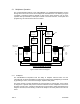
3 Hardware Installation The Nx8-DualMUX system hardware is designed for ease of installation and maintenance. The following sections provide important details on the physical design of the system and proper utilization of these design features. Front and rear views of the complete Nx8DualMUX system with configurable power supply redundancy are shown in Figure 10. Redundant systems differ from non-redundant systems only in the number of power supplies and AC power connectors.
The Nx8-DualMUX system is comprised of the following user-accessible modules: Main Chassis Power Supplies ( 1 or 2) Processor Card, Nx64 Port I/O Cards (4) 3.1 Main Chassis The main chassis includes support for AC mains power entry and distribution, backplane interconnections of signals and DC power, external port connectors, and mechanical support for all replaceable cards. Other than the fuse holder, no part of the main chassis should be disassembled or removed by the user at any time 3.1.
Side outflow Convection (through unit) Nx64-MUX Side inflow Figure 11 Airflow around obstructions 3.2 Power Supply Modules The power supply is a user-replaceable, plug-in module that furnishes DC power to the system derived from the AC power source. All power buses that interconnect the system modules are distributed via the internal backplane. Power supplies may be either single, or 1:1 redundant, depending on the type of system shipped.
3.3.1 Processor Card Replacement The processor card may be replaced with power applied to the system, but it is recommended that the process of removal and insertion be carried out with AC power OFF. There is no information preserved by keeping the AC power on the system while the processor card is replaced. The processor card may be removed by unlocking the plug-in via the two front panel locking screws, and pulling on the U-shaped card pull mounted on the front panel.
NORMAL CONDITION ABNORMAL CONDITION FIRST ACTION AC mains power is OK AC line fuse is blown Defective System: NOTE: Do not replace fuses return system to factory for repair.
166119 34 8/31/2006
4 User Interface 4.1 Indicators 4.1.1 Processor Card The Processor card has fourteen LED indicators on its front panel as shown in Figure 13. Each indicator‟s definition is as follows: POWER (Green) – When ON indicates that the power supply is providing regulated DC power to the system. IMPORTANT NOTE: If this indicator is OFF, the operator should check before assuming that AC Mains power is not applied to the system. SYS (Bi-color; Yellow and Green) – General system status.
PT# 166102 MODEL: PROCESSOR, Nx-MUX S SY A ST Nx-MUX S TU N SY C C RX C TX D RX D TX POWER P O LO A COMPOSITE B NOTICE: DISCONNECT AC POWER SOURCE BEFORE REMOVING THIS MODULE Figure 13 Processor Card Front Panel 4.1.2 Port I/O Card The Processor card has eight LED indicators on it‟s front panel as shown in Figure 14, arranged in four groups of two LED‟s each. The meaning of each pair of indicators is the same, although each pair applies to a different port.
PT# 166007 MODEL: 4-PORT I/O VE H +1 C TI AC H +1 LO C O P TI H +2 VE AC C H +2 LO C O P TI C H +3 VE AC H +3 LO C O VE P TI C H +4 AC H +4 LO O P C Figure 14 Port I/O Card Front Panel 4.1.3 Redundant Power Supply In systems configured with redundant power supplies, the front panel of each supply has a single two-color (green/yellow) LED that indicates the operational state of the associated DC power supply.
Table 13 – Console Terminal Interface Settings Additionally, the Nx8-DualMUX console interface is designed to echo characters as they are received from the terminal, therefore the terminal or emulation program should not locally display characters as they are sent. 4.2.1.1 Console Connection and Session Initiation A standard RS-232 modem interface cable between the Nx8-DualMUX and the PC or terminal is used for console connectivity.
The operator is automatically logged off the system when there is no terminal keyboard activity for a period of 30 minutes. The operator may also perform a Log Off command by selecting option [6] on the Top-level menu screen. 4.4 Menu and Screen Format All menu screens adhere to the display format of Figure 16 (as shown for the Hyperterminal application). ~ Nx8 ID: xxxxx Sys:3.2 FPGA:3.
4.5 Menu Structure In order to illustrate the menu hierarchy in an abstract way, a graphical representation of the menu structure is used in this document. The following diagram shows the general symbols used in these illustrations and how they are used to construct a menu tree.
4.6 Help Menu The Help Menu (option [7] on the Top-level menu screen) provides information on interpreting the status area of the screen and commonly used menu navigation functions. The operator should be familiar with the contents of the Help menu, shown in Figure 18 and refer to it frequently when learning to operate the system. ~ Nx8 ID: xxxxx Sys:3.2 FPGA:3.
4.7 Top-Level Menu The top-level menu provides eight optional menus from which to set-up and conduct system operations, as shown in Figure 19 below. TOP-LEVEL SYSTEM MENU 1 Composite Link Statistics 2 Composite Configuration Menu 3 Channel Configuration Menu 4 Status/ Configuration Functions Menu 5 Test/ Maintenance Menu 6 Log Off 7 Help 8 About Figure 19 The following sections outline choices 1 through 5, enumerated by the menu option number. 4.7.
~ Nx8 ID: xxxxx Sys:3.1 FPGA:2.2 Ser:0 00017:21:51 ~- CpA=L CpB=L Channels: A A A A A A A A B B B B B B B B LPwr=x+ RPwr=..
Option [4] : Set Composite B Recover Threshold Same as option [2], but applies to Composite link B. Option [5] : Clear „Hits over last xxxxx:xx:xx' Counters nd Clears the 2 line of error count registers and restarts the elapsed timer. 4.7.2 Composite Configuration Menu [2] The Composite Configuration Menu allows the operator to set up all parameters associated with the operation of both composite ports, including those of the remote system when linked.
In this menu the operator begins by choosing the composite port to which subsequent menu operations and commands will be directed. Once this selection is made the command menu options, 1 through 10 are presented. In this way, the operator may set unique parameters for Local versus Remote systems, and Composite A versus Composite B. Some of the menu selections however, automatically update the corresponding parameter on both Local AND Remote systems.
Option [3]- EIA-530 Option [4]- HI-Z (Off) Selecting this last option turns off the Composite port interface drivers. 4.7.2.4 Composite Link Timing Source[4] This menu allows selection of the source of the timing for the composite link. Clocks for all channels are derived from this source. When the TxCE driver is enabled, it‟s clock input is taken from the clock selected in this menu.
Option [7] - 60 seconds Option [8] - 5 minutes 4.7.2.9 Composite Link Restore Holdoff Timer [9] This menu allows setting the time period after link synchronization (SYNC) returns before the link is declared to be in service and available for re-assignment of channels Option [1] – Immediate Option [2] - 1 second Option [3] - 5 seconds Option [4] - 10 seconds Option [5] - 30 seconds Option [6] - 60 seconds Option [7] - 5 minutes 4.7.2.
The following diagram depicts the menu/options tree for the Channel Configuration Menu: 3 Channel Configuration 1 1-16 Local Channel Configuration 1 Channel State Channel Selection Select Channel 2 2 Channel Port Rate Channel # Remote Channel Configuration 3 Channel Port Type 4 Channel Port TxD Clock Signal 5 Channel Port RTS/CTS Delay 6 Channel Port DCD Source 7 Channel Failover Mode 8 Channel Failover Rate 9 Channel Restoral Timer 10 Channel Loop Modes [1]- Unsuspend Channel
configuration, such as the type of electrical interface of the port, which may be different on the local side from the remote side. On the other hand, most channel parameters, for example, channel rate, apply to both local and remote ports. After choosing a local or remote context, the operator then chooses the channel number to which subsequent commands will be directed. Once this selection is made the command menu options, 1 through 12 are presented and the commands will only apply to that channel.
4.7.3.3 Channel Port Type [3] This menu allows the selection of the type of port interface standard used at the selected port. RS-232 is available on all ports, whereas EIA-530, X.21 and V.35 are available only on the first port of each port card. It is not required that the port electrical type be the same for a given channel on each end of the link, but it is not possible to apply async and synchronous formatted data on opposite ends of the same channel.
4.7.3.7 Channel Failover Mode [7] The Channel Failover Mode determines the priority a channel has under conditions where a composite link has failed and channels are re-assigned to the backup link. Low Priority and Fixed Low channels on a non-failed link may be “bumped”, or suspended from service when a High Priority channel is re-allocated from a failed link. Any channel that is in “fixed” mode (Options 3 & 4), will not move to a surviving link should it‟s home link fail.
receive data signal of the DTE in place of that from the multiplexer port. While this loop is in effect, a continuous MARK signal is provided to the transmit data input of the port. [3] - Remote Loopback Selecting this option causes receive data from the multiplexer port to be looped back to the transmit data signal of the same multiplexer port in place of that from the DTE. While this loop is in effect, a continuous MARK signal is provided on the receive data output to the DTE.
system, when linked up, is loaded from the file. The configuration is NOT stored to FLASH memory by this command 4.7.4.5 Store/Reload Local and Remote Configurations to/from each Flash [8 & 9] Selecting either of these two options will cause the current active configuration to be either stored to FLASH memory, or to be reloaded from FLASH memory, respectively. This command operates on both local and remote systems. When powering up a system, FLASH memory is used to retrieve the last saved configuration.
4.7.4.9 Reset to Null Configuration Selecting this option causes the current active local configuration to the reset to a “null” configuration. The following image of the configuration status display (Figure 25) indicates the state of the local system in a null configuration: ~ Nx8 ID: xxxxx Sys:3.2 FPGA:3.2 Ser:0 00007:34:32 ~- CpA=o CpB=o Channels: X X X X X X X X X X X X X X X X LPwr=+x RPwr=..
4.7.5 Test & Maintenance Menu [5] This menu presents several options for collecting information on the system status of the local and remote systems, and allows control over some “housekeeping” functions.
4.7.5.4.1 Change Password [1] This option allows an operator who is logged in, to change the password on the selected system. Passwords may be different on local and remote systems. When changed, the password is updated immediately in FLASH memory. 4.7.5.4.2 Change NodeID [2] This command allows the NodeID to be changed. Valid characters include upper and lowercase alphabetical characters, numerals, and underscore. Invalid characters may be typed but are not accepted.
166119 57 8/31/2006
166119 58 8/31/2006
5 Appendix 5.1 Factory Default Configuration (Null Configuration) Systems are shipped with a factory-default configuration to provide a starting point for the operator to configure the system and establish limited, basic functionality of the hardware. The factory default configuration may be restored in working configuration memory at any time by executing the Null Configuration Reset command. Table 14 summarizes the settings stored in systems upon shipping to the customer.
5.2 Connector Pinout Diagrams 5.2.1 Channel Port Connectors (DCE) 13 12 25 11 24 9 10 23 22 8 7 21 20 6 19 5 18 4 17 3 16 1 2 15 14 25-pin Sub-Miniature D-type Connector with Sockets (female) Signal Pin No. RS-232 Mode EIA-530 Mode (Ports 1, 5, 9, & 13 only) V.
5.2.2 Composite Port Connector (DTE) 1 2 14 3 15 4 16 6 5 17 18 7 19 8 20 9 21 10 22 11 23 13 12 24 25 25-pin Sub-Miniature D-type Connector with Pins (male) Signal Pin No. RS-232 Mode EIA-530 Mode V.
5.2.3 Console Port Connector RS-232 Async DCE 13 12 25 11 24 9 10 23 22 8 21 7 20 6 19 5 18 4 17 3 16 1 2 15 14 25-pin Sub-Miniature D-type Connector with Sockets (female) Pin No. Signal 1 Frame GND 2 TxD 3 RxD 4 RTS 5 CTS 6 DSR 7 Signal GND 8 DCD 20 DTR Note: undesignated pin No.
5.3 Adapter Cables 5.3.1 Composite Port V.35 Adapter Cable Connection Diagram Use the following diagram when constructing or specifying an adapter cable between the Nx8-DualMUX Composite port and a standard V.35 cable, or DCE device. V.35 mode 25-pin Female Sub-miniature D V.
5.3.2 Composite Port X.21 Adapter Cable Connection Diagram Use the following diagram when constructing or specifying an adapter cable between the Nx8-DualMUX Composite port and a standard X.21 cable, or DCE device. EIA-530 mode 25-pin Female Sub-miniature D X.
5.3.3 Composite Port RS-449 Adapter Cable Connection Diagram Use the following diagram when constructing or specifying an adapter cable between the Nx8-DualMUX Composite port and a standard RS-449 cable, or DCE device.
5.3.4 Channel Port V.35 Adapter Cable Connection Diagram Use the following diagram when constructing or specifying an adapter cable between any Nx8-DualMUX Channel port operating in V.35 mode and a standard V.35 cable, or DTE device. V.35 mode 25-pin Male Sub-miniature D V.
5.3.5 Channel Port X.21 Adapter Cable Connection Diagram Use the following diagram when constructing or specifying an adapter cable between any Nx8-DualMUX Channel port operating in EIA-530 mode and a standard X.21 cable, or DTE device. EIA-530 mode 25-pin Male Sub-miniature D X.
5.3.6 Channel Port RS-449 Adapter Cable Connection Diagram Use the following diagram when constructing or specifying an adapter cable between any Nx8-DualMUX Channel port operating in EIA-530 mode and a standard RS-449 cable, or DTE device.
5.3.7 Channel Port-to-Console Adapter Cable Any Nx8-DualMUX channel port, with a management terminal attached, may be used to directly access the menu-driven user interface on a remote Nx8-DualMUX by cabling the corresponding channel port on the remote system to the console port. Once the end-to-end channel is configured properly, an operator at the local end of the link can perform menu operations on the remote system.
5.4 Configuring an Nx8-DualMUX Link for Simplex Operation The Nx8-DualMUX may be used to support Simplex network traffic. Since the multiplexer is designed to normally provide full duplex operation, simplex configurations are by nature, special cases, and certain features of the multiplexer will be unavailable or inoperative. Also, because the multiplexers at each end of the link are not equivalent in function, the differences must be accounted for when setting up and configuring the systems.
One method to work around the problem of implementing differing local and remote channel parameters, is to remove the transmit loop at the sending end of the link for the duration of the configuration change. While the transmit loop is down, the sending end will neither send nor receive user channel data, but will continue to produce a framing pattern along with the inband management channel.
5.5 4-Port (Channel) I/O Card(s) Four Ports: DB-25 Females, Four ports RS-232, one port Software Selectable for RS-232, RS-530, V.35*, RS422/449* and X.21* ( *- Adapter cable required for connector standard) Maximum 4 cards per chassis, 16 channel ports per chassis Technical Specifications Application Multiple Sync or Async DTE devices time-division-multiplexed onto one or two synchronous DCE communication links and demultiplexed by an identical unit at the far end.
5.6 Ordering Information Part Number: 166100 Model: Nx-MUX_DD Description: 16-Port Dual Composite, Dual Power Chassis QTY Req: 1 Part Number: 166106 Model: Nx-Dual Composite Description: Nx8-Dual Composite Processor Card Qty Req: 1 Part Number: 166007 Model: Nx8-I/O Description: I/O Board, 4-Port, Nx-MUX QTY Req.: 1 to 4 per Mux chassis Part Number: 166080 Model: Nx-SRPS Description: Nx-MUX, Single Redundant Power Supply QTY Req.