
Owner's manual

Operator's Manual
Trail Warrior Quick Split 12-Ton Log Splitters
Check for parts online at www.getearthquake.com or call 800-345-6007 M-F 8-5 21
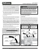
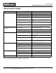
5. Move control lever forward to extend the hydraulic cylinder all
the way. (It is normal for the cylinder to not move smoothly as it
purges the air from the system.) SEE FIGURE 25. For European
models with two valves, while holding the (rear) Flow Control
valve lever in the rearward position with one hand, use the other
hand to move the (front) Direction Control valve lever forward
to extend the hydraulic cylinder all the way. SEE FIGURE 26.
6. Move control lever to the return position until ram is retracted
fully. On European log splitter models with two valves, the
(rear) Flow valve lever must be held in the rearward position
in order for the (front) Direction Control valve lever to retract
the ram when moved rearward.
7. Turn o engine.
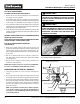
8. With cylinder in the return position with the air bleeder valve
still in the open position, open the ller cap very slowly to
allow any air to escape that may have been trapped in the
reservoir during the initial lling procedure.
9. Top o the reservoir by adding up to 3 more quarts of hydraulic uid.
NOTE: Some units may not take the complete 3 quarts as
they were lled and tested at the factory prior to shipment
and some residual uid still remains in the hydraulic system.
Your Trail Warrior is now properly lled and ready for use. You
have the correct amount of uid in the reservoir when you can
see the uid inside the ll spout. Some ll caps are equipped
with dipstick for checking uid level.
Once the log splitter is lled with uid you can close the air
bleeder valve by turning it all the way clockwise.
TIP: If your ram still does not travel smoothly, there may still be
air in the hydraulic system or your uid level is too low. If this is
the case, with the engine turned o and the ller cap on, open
your air bleeder valve and move the hydraulic control valve
from the forward to return position a few times to purge any
air that may be trapped in the hydraulic system.
NOTE: Doing this procedure with the ller cap removed will
cause any air that is in the system to expel through the ller
spout. Check for proper uid level.
SYSTEM CHECK:
With the correct amount of hydraulic uid in the system, oper-
ate the cylinder ram all the way into the forward direction and
all the way in the return direction. Check that the ram moves
smoothly without jerking. Check that there is no leaking of uids
at component ports, ttings, or hoses. If leaking is found, tighten
ttings or clamps until leaking goes away. If leaking doesn't go
away, contact Ardisam Customer Service (800-345-6007 M-F
8:00-5:00 PM CST, or e-mail info@ardisam.com).
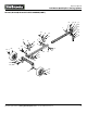
Figure 25
: US Version
FORWARD
(Splitting Direction)
REARWARD
(Return Direction)
NEUTRAL
POSITION
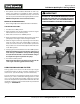
Figure 26
European Version
FORWARD
(Splitting Direction)
REARWARD
(Return Direction)
DIRECTION
CONTROL VALVE
FRONT VALVE
W1265V0700ACE
NEUTRAL
POSITION
REARWARD
ONLY
(Flow On)
NEUTRAL
POSITION
FLOW
CONTROL VALVE
REAR VALVE
W1265V0700BCE
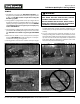
WARNING
FLUID ESCAPING FROM A VERY SMALL HOLE CAN BE
VERY DIFFICULT TO SEE. DO NOT CHECK FOR LEAKS
WITH YOUR HAND. ESCAPING FLUID UNDER PRES
SURE CAN HAVE SUFFICIENT FORCE TO PENETRATE
SKIN, CAUSING SERIOUS PERSONAL INJURY OR EVEN
DEATH. LEAKS CAN BE LOCATED BY PASSING A PIECE
OF CARDBOARD OR WOOD OVER THE SUSPECTED
LEAK. LOOK FOR DISCOLORATION.