
Datasheet


99
PCB Pushbuttons
38
07.2008
Essential Accessories:
d Lens plate double page 41
d Marking plate double page 41
d Single-LED page 43
Continuation see next page
Contacts: NC = Normally closed, NO = Normally open
Switching action: MA = Maintained action, M = Momentary action
Terminals: P = PCB terminal
Component layout from page 46, Mounting dimensions from page 47, Technical drawing from page 48, Circuit drawing from page 49
Essential Accessories:
d Lens plate triple page 41
d Marking plate triple page 41
d Single-LED page 43
Continuation see next page
Contacts: NC = Normally closed, NO = Normally open
Switching action: MA = Maintained action, M = Momentary action
Terminals: P = PCB terminal
Component layout from page 46, Mounting dimensions from page 47, Technical drawing from page 48, Circuit drawing from page 49
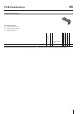
Illuminated pushbutton actuator double
Front protection
Contacts
Switching action
Terminals
a 18.6 x 37.8
Typ-Nr.
Component layout
Mounting dimensions
Technical drawing
Circuit drawing
e
Illuminated pushbutton actuator double IP 40 1 NC + 1 NO MA P 99-418.837 2 1 2 5 0.013
M P 99-408.837 2 1 2 13 0.013
2 NO MA P 99-416.837 2 1 2 8 0.013
M P 99-406.837 2 1 2 16 0.013
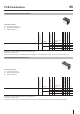
Illuminated pushbutton actuator triple
Front protection
Contacts
Switching action
Terminals
a 18.6 x 56.9
Typ-Nr.
Component layout
Mounting dimensions
Technical drawing
Circuit drawing
e
Illuminated pushbutton actuator triple IP 40 1 NC + 1 NO MA P 99-448.837 3 1 3 6 0.019
M P 99-438.837 3 1 3 14 0.019
2 NO MA P 99-446.837 3 1 3 9 0.019
M P 99-436.837 3 1 3 17 0.019
38