
Datasheet
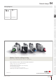


Illuminated pushbutton square, IP65
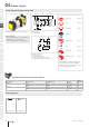
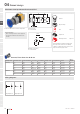
Equipment consisting of (schematic overview)
Front bezel Page 202
Lens Page 199
Lens holder Page 201
Actuator
Bayonet ange Page 203
LED Page 204
Lamp block Page 210
Switching element Page 213
Each Part Number listed below includes all the
black components shown in the 3D-drawing.
To obtain a complete unit, please select the red
components from the pages shown.
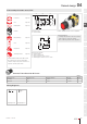
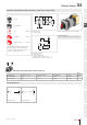
Dimensions [mm]
A = Screw terminal
Product can differ from the current conguration.
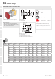
Mounting cut-outs [mm]
A = Screw terminal
B = Push-in terminal (PIT)
C = Plug-in terminal 6.3 mm x 0.8 mm
D = Double plug-in terminal 6.3 mm x 0.8 mm
General information
• Frontring with protective cover to be mounted
with a torque of 0.4 Nm onto actuator
• Max. 3 switching elements can be clipped on
Actuator, Front dimension 30 mm x 30 mm
Switching action Housing colour Housing material Part No.
Wiring
diagram
Momentary Black Plastic 704.731.0 72
Grey Plastic 704.731.1 72
Maintained Black Plastic 704.732.0 73
Grey Plastic 704.732.1 73
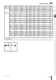
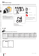
Wiring diagrams
Wiring diagram 72 Wiring diagram 73
Raised design
eao.com § 07/2019
128
04
01
02
03
04
09
14
17
18
19
22
31
41
45
51
56
57
61
70
71
82
84
92
96
13 69
2 ... 7
23
40
A A
30 min.
50 min.
65 min.
Ø22.3
+0.4
0
D
B
A
C