
Datasheet


8
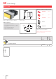
Flush design
84
7
10 max.
49.6 x 23.5
NJO
NJO
3NBY
1ed
c
2
3
4
1fg
h
2
3
4
1ed
c
fg
h
2
3
4
1de
c
fg
h
2
3
4
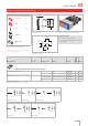
Wiring diagram 1 Wiring diagram 2 Wiring diagram 3 Wiring diagram 4
ed
c
fg
h
1
2
3
4
Wiring diagram 5
Illuminated pushbutton single headed, IP 40
Product can differ from the current configuration. Dimensions [mm]
Mounting cut-outs [mm]
Additional Information
• For front dimension 24 x 48 mm
• For LED element fitting information see
«Application guidelines»
• Has two independent lamp bases
• Light barrier ordered separately
Equipment consisting of (schematic overview)
Front bezel Seite 17
Lens Seite 13
LED Seite 22
Actuator
Fixing sleeve
Each Part Number listed below includes all the black
components shown in the 3D-drawing.
To obtain a complete unit, please select the red com-
ponents from the pages shown.
Contacts Switching action Terminal Part No.
Wiring
diagram
Weight
Illuminated pushbutton actuator single-headed
1 C B Screw 03-616.011 1 0.070 kg
C Screw 03-618.011 2 0.070 kg
2 C B Screw 03-617.011 3 0.075 kg
C Screw 03-619.011 4 0.075 kg
B - C Screw 03-620.011 5 0.075 kg
Contacts: C = Changeover
Switching action: B = Momentary, C = Maintained
03