
Datasheet


5
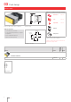
Flush design
784
10 max.
49.6 x 23.5
NJO
NJO
3NBY
c
d
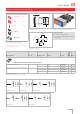
U
1=30-55 VAC
35-75 VDC
U
2=10-35 VAC
1
0-50 VDC
e
f
g
h
f
g
h
Continous
tone
c
d
e
Intermittent tone
approx. 3Hz
Volume control
Wiring diagram 1
Buzzer, IP 40
Product can differ from the current configuration. Dimensions [mm]
Mounting cut-outs [mm]
Additional Information
• For front dimension 24 x 48 mm
• Further information see «Technical data»
Equipment consisting of (schematic overview)
Front bezel Seite 17
Buzzer
Fixing sleeve
Each Part Number listed below includes all the black
components shown in the 3D-drawing.
To obtain a complete unit, please select the red com-
ponents from the pages shown.
Operating voltage Front cap Terminal Part No.
Wiring
diagram
Weight
Buzzer
10 ... 55 VAC, 10 ... 75 VDC Plastic black Screw 03-810.001 1 0.060 kg
03