
Datasheet


4
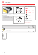
Flush design
60
7
10 max.
49.6 x 23.5
NJO
NJO
3NBY
1
2
3
4
Wiring diagram 1
Indicator, IP 40
Product can differ from the current configuration. Dimensions [mm]
Mounting cut-outs [mm]
Additional Information
• For front dimension 24 x 48 mm
• For LED element fitting information see «Applica-
tion guidelines»
• Has two independent lamp bases
• Light barrier ordered separately
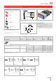
Equipment consisting of (schematic overview)
Front bezel Seite 17
Lens Seite 13
Single-LED Seite 22
Actuator
Fixing sleeve
Each Part Number listed below includes all the black
components shown in the 3D-drawing.
To obtain a complete unit, please select the red com-
ponents from the pages shown.
Terminal Part No.
Wiring
diagram
Weight
Indicator actuator
Screw 03-021.001 1 0.045 kg
03