
Datasheet


11
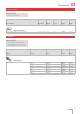
Flush design
75
10
10 max.
49.6 x 23.5
26
NJO
NJO
3NBY
ed
c
fg
h
Wiring diagram 1
B
A
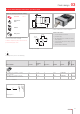
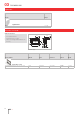
Keylock switch with keylock front bezel, 2 positions, IP 40
Product can differ from the current configuration. Dimensions [mm]
Mounting cut-outs [mm]
Additional Information
• For front dimension 24 x 48 mm
• Front plastic grey
• After turning the key 90° clockwise, the switch
can be operated
• In the unlocked switch positions always perform a
momentary action
• Keylock number: Schulte YB1
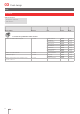
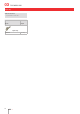
Equipment consisting of (schematic overview)
Front bezel Seite 17
Keylock front
bezel
Actuator
Fixing sleeve
Each Part Number listed below includes all the black
components shown in the 3D-drawing.
To obtain a complete unit, please select the red com-
ponents from the pages shown.
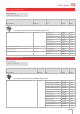
Switching positions (A = Rest, B = Momentary)
Product attribute Contacts
Switching
angle Key remove Terminal Part No.
Wiring
diagram
Weight
A = lockable, non-actuated, B = lockable,
key not removable
2 C B = 90° A Screw 03-695.011 1 0.065 kg
A = lockable, non-actuated or actuated;
can be used with protective cover 03-925
2 C B = 90° A Screw 03-198.011 1 0.065 kg
Contacts: C = Changeover
03