
Manual


USER GUIDE
89
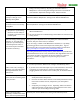
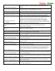
2nd Rudder Rx In %
The measured pulsewidth at the Vector’s 2
nd
Rudder input, if used
Aileron/M2 Output %
The pulsewidth being sent to the Vector’s Aileron/M2 output (0% = 1 millisecond,
100% = 2 milliseconds)
Elevator/M3 Output %
The pulsewidth being sent to the Vector’s Elevator/M3 output
Throttle/M4 Output %
The pulsewidth being sent to the Vector’s Throttle/M4 output
Rudder/M1 Output %
The pulsewidth being sent to the Vector’s Rudder/M1 output
Aux1/M5 Output %
The pulsewidth being sent to the Vector’s Aux1/M5 output, if configured
Aux2/M6 Output %
The pulsewidth being sent to the Vector’s Aux2/M6 output, if configured
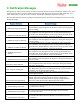
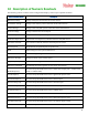
G-Force X Axis
The g-force measured in the X axis
G-Force Y Axis
The g-force measured in the Y axis
G-Force Z Axis
The g-force measured in the Z (vertical) axis
Pitch
The amount of pitch from level, in degrees
Roll
The amount of roll from level, in degrees
Yaw
The amount of yaw motion, in degrees (When the compass is enabled and
properly calibrated, this represents the heading relative to true North)
Climbrate
The model’s present climbrate
Vario(TEC Climbrate)
The model’s present climbrate, after Total Energy Compensation has been applied
GPS Satellite Count
The number of satellites in view, as reported by the GPS
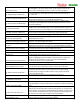
Receiver RSSI
The present RSSI %
GPS Groundspeed
The present ground speed of the model, as reported by the GPS
GPS Altitude
The zero referenced altitude, as reported by the GPS
GPS Course
The present true course heading, as reported by the GPS
GPS HDOP
The present HDOP, as reported by the GPS
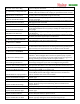
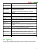
Spektrum Rx Holds
Receiver health information from the Spektrum™ Flightlog™ data port. Find the
Spektrum™ Flightlog™ manual online for more information
Spektrum Lost Frames
“”
Spektrum Ant A Fades
“”
Spektrum Ant B Fades
“”