
Manual


USER GUIDE
88
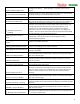
10 Description of Numeric Readouts
The following numeric readouts can be configured for display. Some require optional hardware.
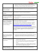
Numeric Readout Name
Description
Main Pack Voltage
Voltage of the pack connected to the current sensor
Transmitter Voltage
Voltage at the "Vid Tx” power connection of the video harness
Camera Voltage
Voltage at the "Cam/Mic” power connection of the video harness
Receiver Voltage
Voltage at the Vector’s servo outputs
Sensor Temperature
Temperature of the optional temperature sensor
Ambient Temperature
Approximate air temperature, obtained from the GPS/MAG sensor
Barometric Altitude
Zero referenced altitude, from the onboard pressure sensor
Pitot Airspeed
Airspeed from the optional pitot airspeed sensor
RPM
RPM reading from the optional RPM sensor
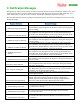
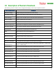
Main Pack Current
Current flowing through the current sensor
Main Pack Wattage
Voltage X Current at the current sensor
Prop RPM (Headspeed)
Same as RPM reading above
Main Pack mAH Used
The milliamp hours through the current sensor since bootup
Mode Rx Input %
The measured pulsewidth at the Vector’s mode switch input (0% = 1 millisecond,
100% = 2 milliseconds)
Gain Rx Input %
The measured pulsewidth at the Vector’s gain knob input, if used
Aileron Rx Input %
The measured pulsewidth at the Vector’s aileron input
Elevator Rx Input %
The measured pulsewidth at the Vector’s elevator input
Throttle Rx Input %
The measured pulsewidth at the Vector’s throttle input
Rudder Rx Input %
The measured pulsewidth at the Vector’s rudder input
Submode Rx Input %
The measured pulsewidth at the Vector’s submode switch input, if used
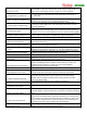
Kill Switch Rx In %
The measured pulsewidth at the Vector’s kill switch input, if used
2nd Aileron Rx In %
The measured pulsewidth at the Vector’s 2
nd
Aileron input, if used
2nd Elevator Rx In %
The measured pulsewidth at the Vector’s 2
nd
Elevator input, if used