
Manual


USER GUIDE
76
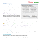
Vario Averager Seconds: This setting controls the averaging period of the variometer, in 10ths of a second
units. For faster response, lower periods are recommended, but in rougher air longer periods may be required
to avoid false alarms.
Vario Minimum Sinkrate (Deadband): This setting controls the minimum sinkrate. Normally, this would
be set to the standard sinkrate of your model, i.e., the rate at which it descends in smooth air with no thermals.
When you descend at a rate greater than this sinkrate, the variometer will start to sound
Vario Minimum Climbrate (Deadband): This setting controls the minimum climbrate. When you ascend at
a rate greater than this climbrate, the variometer will start to sound,
Set Vario Audible Tone Gain: This setting changes the amount the variometer pitch changes as the climbrate
increases or decreases. If you are not hearing enough change, increase this parameter, and vice versa for too
much frequency change.
Total Energy Comp Percent: This adjusts the scaling of the Total Energy Compensation calculation. 100%
means that Kinetic Energy is converted into Potential Energy directly, i.e., any change in airspeed is assumed to
directly negate any change in altitude. Less than 100% reduces the degree which airspeed change affects Total
Energy, and increasing it above 100% increases the amount.
Vario Off when Motor Running: This option disables the variometer tones when the motor is running, based
on the amperage draw of the motor. This is useful for “motor
gliders.” The variometer is off when motor current is more
than approximately 1.5 amps.
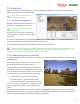
7.7 Vector Calibration
The Vector is factory calibrated, and normally no further
calibration is necessary. However, user calibration of some
sensors can be performed. Calibration options are located on
the “Calibration and Sensor Setup” menu.
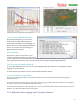
7.7.1 Electrical Calibration
The voltage and amperage (current) readings for your motor
pack, and the voltage readings for your transmitter pack,
camera pack and receiver pack (if used) can be calibrated.
These calibrations are performed in the “Electrical Calibration”
menu. For your convenience, all voltages and currents are
displayed in real time on the electrical calibration page, so you
can compare the Vector readings with the readings of your
voltage and current meter as you change the settings.
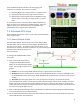
Voltage Calibration: To calibrate voltages, change the “Voltage
Factor” for the appropriate voltage. Increasing the factor
increases the reported voltage, and vice versa.
Current Calibration: Calibrating the current sensor typically involves just increasing or decreasing the
“Current Sensor Factor” as appropriate.
One additional calibration setting for the current sensor is the “Zero Offset”. The zero offset is chosen to match
the lowest level of current flow that the Vector’s current sensor can detect. Typically, this is about 300 mA (0.3
amps).