
Manual


USER GUIDE
69
Gauge/Swatch BEST Value: Here, you enter numeric value of the readout that you want to always display the
green color. If a lower number is better for the readout, such as with altitude, you would enter the lowest
value here. If a higher number is better, such as with voltages, you would enter the highest number here.
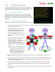
Please see the examples at right. For the “Transmitter Voltage”
readout, the best value is set to 12.60 and the worst is 10.80. The
gauge will be green and show full at 12.60V or higher, and will show
empty and be red at 10.80V or lower.
For the “Barometric Altitude” readout, the best value is set to 0, and
the worst value is set to 400. The gauge will be green and show empty
at 0 or lower, and will show full and be red at 400 or higher.
Until you enter the WORST value below, and autofill the thresholds, a warning about the thresholds
being incorrect will appear at the bottom of the menu. This is normal.
Color Threshold 1, Color Threshold 2, Color Threshold 3,
Color Threshold 4: The color thresholds let you set the values for the readouts where the color changes will
occur. The simplest way to set these up is to set up the best and worst values, and select “Autofill Thresholds”
below. This will divide the thresholds equally between the best and worst values. Or, you can manually
change them if you want a different distribution.
Gauge/Swatch WORST Value: Here, you enter numeric value of the readout that you want to always display
the red color. If a lower number is worse for the readout, such as with voltage, you would enter the lowest
value here. If a higher number is worse, such as with altitude, you would enter the highest number here.
Autofill Thresholds!: Select this item to autofill the color thresholds as described above.
7.1.2.4 Special note about the Motor Voltage (Pack Voltage) Readout
For the Motor Voltage readout, the values entered for thresholds need to be per-cell voltages (i.e., 4.2), rather
than overall pack voltages. The Vector automatically detects the cell count for your pack, so you can switch
between packs of different cell counts, without needing to reset the pack voltage swatch settings each time.
7.1.3 The Advanced Graphics/Indicators Menu
The menu is similar to the basic Graphics/Indicators menu, except that it allows you to select the OSD screens
on which the graphics and indicators appear, and you can also enable display of additional battery gauges and
waypoints in this menu.
7.2 Using Optional RPM and Temperature Sensors
The Vector supports both an external temperature sensor (micro or loop type) and a brushless RPM
sensor. As of this writing, the existing Eagle Tree temperature and RPM sensors require modifications
to work with the Vector. Eagle Tree plans to release Vector versions of these sensors later.
7.2.1 Temperature Sensor
Assuming the Aux2/M6/Temp Vector port is not being used to control a servo or motor output, you can
connect a MODIFIED Eagle Tree “Micro Temp Sensor” (P/N TEMP-MICRO) or “Motor Loop Temp Sensor” (P/N
TEMP-LOOP) to that port, and display and log temperature.
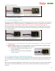
The simple modification of the sensor involves carefully removing the sensor’s bottom wire from the servo
housing, using a probe or needle to gently lift the tab on the housing, and placing that wire in the top position of