
Manual


USER GUIDE
66
6.4.2 RTH Ground Testing
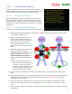
If RTH is configured correctly, after your GPS as acquired a fix and the home position is set, when you turn your
transmitter off (ON THE GROUND) the “RTH Engaged…” message should appear in the OSD notification area of
the video screen. Additionally, the Flight Mode Indicator on the video screen should change to “RTH”. If you
don’t see BOTH these notifications, RTH will not activate in the event of a receiver failsafe. Please refer back to
the RTH configuration section if RTH does not trigger correctly.
For fixed wing models, don’t forget that your propeller may spin at any time when RTH is triggered, even
on the ground!
6.4.3 In-air RTH Testing
The simplest way to test RTH in the air is to program a mode/submode switch position to “RTH Test”. When
this switch position is selected, RTH should engage, and your model should fly toward the home point.
Never intentionally turn off your radio to test RTH in the air. There is a chance that your receiver will
not link back up with your radio, which could result in a crash!
When in RTH test mode, moving the control stick causes RTH to disengage, and the model switches to 2D with
Hold flight mode.
Note: if your multirotor is in Polar or Cartesian flight mode and RTH Test is triggered, remember that it will
switch to 2D with Hold flight mode during the RTH testing, so the control stick will control the multirotor
differently during RTH testing!
If you find that your model returns home correctly, no further adjustments should be necessary. If problems
occur, refer to the Troubleshooting chart later in the document.
Don’t forget to switch out of RTH Test mode before landing!
7 Advanced Vector Setup and Calibration
This section covers some of the many Vector settings and features that will appeal to more advanced pilots.
7.1 Advanced OSD Setup
The Advanced OSD configuration tools let you configure many additional readouts with multiple display
options, set up multiple screens of readouts, set customized messages to display for alarms, enable additional
voice options, and many more features. See section 10 for a complete list of numeric readouts available.
It is generally faster and more intuitive to do advanced OSD configuration with the software, but full
stick menu support is provided.
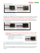
7.1.1 The Advanced Numeric Readouts Menu
Advanced numeric configuration through the stick menus is done by
navigating to the "Advanced Numeric Readouts...." menu from the OSD
Setup menu.
If you add advanced readouts to the display screen that are not
available on the basic readouts menu, problems can occur if you try to
add additional readouts later, using the basic menu. later.