
Manual


USER GUIDE
55
If the OSD information is too wide for your screen, select Narrow Screen Mode.
If you have trouble reading the text, try changing the black level, or changing the colors of the text, as described
below.
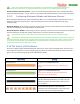
To change color settings, select the “Color Setup” menu. You can change the color brightness, intensity, and
hue in this menu. Also, you can select which colors to use for text and graphics.
If you prefer an entirely black and white display, select “white” for the colors of each item, and “black”
for the highlight of each.
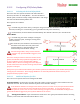
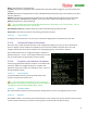
5.14.2 Setting Display Units (English or Metric)
To set the displayed units, navigate to the “English/Metric
Units Setup” menu, from the main stick menu.
The Vector lets you set the overall system units, and
if desired, different units for individual classes of readouts
(speeds, distances, and altitudes).
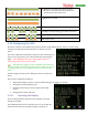
5.14.3 Choosing what to Display on
the OSD Screen
The Vector’s displayed information is divided into three
classes:
Numeric readouts - numeric readouts are displayed
on the first two rows and last two rows of the
display. Examples: RSSI, motor battery voltage.
Graphics and Indicators– these are displayed in several different places on the screen. Examples:
altitude and airspeed ladders, compass.
Notification area – status and warning messages are displayed in this area
To configure basic numeric readouts that are typically used, select the “Numeric Readouts Setup” menu item
from the OSD Setup menu. Here’s a description of these readouts:
5.14.4 Basic Numeric Readouts
Here is some information on the basic numeric readouts available:
5.14.4.1 Electrical Readouts
Pack Voltage, Pack Current, Pack mAH Used: These display
information about your main flight pack, which must be connected
to the current sensor for these readouts to be valid.
Video Tx Voltage: This is the voltage being supplied to the “Vid Tx”
plug “E” on the video harness. This readout would normally be displayed only if you are using a second video
battery.
Receiver Voltage: This is the voltage being supplied via the red wire of the receiver connection harness, or via
the power pins of the Vector servo outputs.