USER GUIDE Vector Flight Controller + OSD User Guide March, 2015 Version 2.2 Software Version 11.
USER GUIDE Table of Contents 1 Safety ............................................................................................................................................................................. 6 1.1 .... Read the Manual!................................................................................................................................................................6 1.2 .... Special Symbols used in the Manual ..................................................................
USER GUIDE 4.2 .... Mounting the GPS/MAG Sensor ................................................................................................................................ 27 4.2.1 GPS Signal Interference ......................................................................................................................................................... 27 4.2.2 Magnetometer Interference .................................................................................................................
USER GUIDE 5.11.3 Confirming ESC Endpoints are set Correctly (Multirotor only) ................................................................... 46 5.11.4 Arming and Disarming your Multirotor (Multirotor only) ............................................................................ 47 5.11.5 Setting Idle Throttle (Multirotor only) ................................................................................................................... 48 5.11.
USER GUIDE 6.4.2 RTH Ground Testing ............................................................................................................................................................... 66 6.4.3 In-air RTH Testing ................................................................................................................................................................... 66 7 Advanced Vector Setup and Calibration................................................................................
USER GUIDE 1 Safety The Vector is intended to be used exclusively for recreational purposes in model planes, boats and cars. Using the Vector for other purposes is not supported. Further, using the Vector in situations where its use or failure could result in loss of life, bodily injury or property damage is expressly prohibited. Eagle Tree Systems, LLC, is not responsible for your use of this product, or for any damages or injuries you may cause or sustain as a result of its usage. 1.
USER GUIDE RC models and accessories are not toys! The Vector should not be used by children. You should always use a spotter if your eyes are not on your model. For USA customers, please refer to the Academy of Model Aeronautics Safety Code at http://www.modelaircraft.org/files/105.PDF and FPV related code at http://www.modelaircraft.org/files/550.pdf Always obey the law when flying. Most video transmitters used for FPV flying require an amateur radio license to operate legally.
USER GUIDE 2.2 Packing List Your package should include the following: Vector Controller Current Sensor/PSU (DeansTM, XT60TM or wire leads version), GPS/Magnetometer (GPS/Mag), with GPS stand, clip and screw Video, Audio (not shown), GPS, and Receiver Harnesses 2.
USER GUIDE 2.4 How to Get Help and Request New Features Eagle Tree is committed to providing great customer service. Once you’ve read the manual, if something is not clear, just ask. We’d much prefer to take the time to answer your questions, rather than having you waste your valuable time struggling with an issue. To get help 24/7, visit the Eagle Tree Vector support thread on RCGroups: http://www.rcgroups.com/forums/showthread.php?t=2032857 Or, visit the thread on FPVLab: http://fpvlab.
USER GUIDE 2.5.3 Updating your Vector Firmware Even if you will be configuring the Vector using the stick menus, it’s a good idea to keep your Vector firmware updated, in case we add a feature or resolve an issue that is relevant to your airframe. Our latest software always has the latest Vector firmware included with it. To check to see if you have the latest firmware, first check what firmware version is installed on your Vector, which is displayed at the bottom of the Vector boot-up OSD screen.
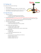
USER GUIDE 2.7 Glossary of Terms used in the Manual Here are definitions for some of the terms used throughout the manual. FPV – FPV stands for First Person View. If you are not familiar with FPV, there are many websites devoted to it. Our FPV overview web page at http://www.eagletreesystems.com/OSD has a brief tutorial on FPV, which is a good place to start. OSD – OSD stands for On Screen Display. The OSD shows flight information, overlaid on the video camera image. RTH – Return to Home.
USER GUIDE Mode Switch – A two or three position switch on your radio transmitter which you have configured to control the “Mod” input on the Vector’s Receiver Connection Harness. Toggle – One fairly rapid movement the Mode Switch between its extents. (UP/DOWN or DOWN/UP) Configuration Gestures – A series of toggles of the Mode Switch. The number of times you toggle the switch determines which configuration step is performed. PSU - Power Supply Unit.
USER GUIDE 3 Connecting the Vector This section describes the Vector’s cabling and connections, and how to connect the Vector to your RC receiver, your servos or ESCs, and your FPV video transmitter and camera. 3.1 Vector Controller Connections The figure below shows the function of each of the Vector’s ports, and other Vector information. 3.1.
USER GUIDE For example, if the backup power is connected to the BEC of your ESC (via your receiver), and that is supplying 5.0V, the Vector will use the PSU power unless the PSU voltage drops below 4.5V. Likewise, if your BEC is providing 6.0V to the backup power port, the backup power port will always be powering the Vector unless the BEC output fails. Note that the backup power input will NOT power your camera or video transmitter.
USER GUIDE 3.3 Vector Current Sensor/PSU Power Output The Vector’s high efficiency and low noise PSU accepts up to 6S voltage input, and provides filtered 5V and up to 12V output at 1A max per channel. It's perfect for powering most FPV gear, and can also power your receiver on multirotors (when NO servos are being powered by the RX!), eliminating the need for an external BEC.
USER GUIDE 3.5 Vector Wiring The Vector’s wire harnesses are shown below. Note that a set of replacement wire harnesses is available (p/n VECCAB-SET). Having additional sets make it easier to move your Vector from model to model. Video Harness – routes video signals, and provides power from the Current Sensor/PSU to the Vector, and optionally to your video transmitter, camera, and microphone. Audio Harness – this cable connects to your microphone, and also to the audio output of your video transmitter.
USER GUIDE The first step to wiring your camera and transmitter is to install servo connectors on the wire harnesses that came with these components, if they don’t have them already. Servo connectors and crimpers are available online or at your local hobby store. Either Futaba™ or JR™ style connectors will work. Refer to the figure at right. Consult the manuals for your camera and video transmitter, identify the signal, power and ground wires, and install the servo connectors on these wires.
USER GUIDE Here are typical wiring strategies, depending on the number of batteries desired, transmitter and camera voltages, etc. Video Setup Wiring Method Single Battery, 12V camera, 12V transmitter Connect both red PSU power taps “A” to camera and transmitter power inputs “D” and “E” Single Battery, 5V camera, 12V transmitter Connect the white PSU power tap “B” to camera power input “D”. Connect a red PSU power tap “A” to transmitter power input “E”.
USER GUIDE Note that the voltage supplied to the red wire of the “Camera/Mic” power input connector “D” on the video harness will be supplied to the red wire on the “Microphn” audio harness connector. 3.5.4 Vector Receiver Harness The Receiver Harness is used to connect the Vector to the outputs of your receiver. The pin-out for the Receiver Harness is shown below. Do not power your receiver with a voltage higher than 16V. The Vector does not power your receiver or servos.
USER GUIDE 3.5.5 Receiver Connection Harness Load Capacity (Fixed Wing Only) With typical fixed wing electric model wiring, the ESC’s BEC is connected to the Vector’s throttle output channel. This BEC powers the servos, and all servos are connected to the Vector’s servo outputs. If you have this configuration, please skip this section. Also, skip this section if you do not have large servos, or if the BEC or battery powering your servos is rated at 6 amps continuous or less (the vast majority are).
USER GUIDE In this case, it’s important that you make sure you never arm your multirotor when the main ESC power connector is disconnected from the Current Sensor/PSU. Or, you can address this issue in some other ways: a) remove/disconnect the red wire from the “Ail” connector, so that power will not pass from your receiver to the ESCs when using the 5V tap to power your receiver. b) Or, remove/disconnect the power servo wire from each ESC.
USER GUIDE 3.5.7 Connecting Receiver and Servos/ESCs to the Vector First, connect your ESC or servo wires to the Vector output ports without powering the Vector, to make sure they reach the desired Vector mounting location. Then disconnect them before proceeding to the configuration section.
USER GUIDE The chart below shows typical receiver and servo/ESC connections for these airframe types. * The Receiver Output and Vector Rx Harness sections do not apply to SPPM or S.BUS™ receiver modes.
USER GUIDE Airframe Vector Airframe Type V-Tail with Ailerons (cont.
USER GUIDE 3.5.8 Connecting you Receiver’s RSSI Output (if available) Note: If you have a PPM capable receiver that outputs RSSI and/or link quality in the PPM stream, instead of through a separate wire, skip to the next section. If you wish to display the receiver’s signal strength (RSSI), and your receiver supports this feature, you will need to connect the top (signal) pin of the “RSSI/5V Backup” connection of the Vector to your receiver’s RSSI output.
USER GUIDE 4 Mounting the Vector and Accessories 4.1 Mounting the Vector 4.1.1 Mounting Location and Orientation Mount the Vector flat and level with the label facing toward the sky and the red arrow on the Vector case facing toward the nose of your model (the direction of forward travel). The Vector should be mounted as near to the model’s Center of Gravity (CG) as practical. Ideally, the Vector will be mounted with the mark shown in section 3.1 (just behind the red arrow) directly above your model’s CG.
USER GUIDE 4.2 Mounting the GPS/MAG Sensor 4.2.1 GPS Signal Interference RF noise from video transmitters, cameras, and other devices can interfere with GPS reception. It’s important to mount the GPS/MAG as far away from these sources as practical. Also, obstructions such as trees or buildings that block the Vector from having a clear, unobstructed view of the sky can cause issues with GPS reception.
USER GUIDE 4.2.4 The GPS Stand and Clip The GPS Stand is designed for multirotors, where it lifts the GPS/MAG sufficiently above the multirotor frame to avoid electromagnetic interference. However, it can be used for any type of model. The stand must be mounted vertically, and the base can be mounted either by placing it under 2 or more of the multirotor’s arm mounting bolts, or with closed cell, double sided foam tape. The stand also has a slot that can be used to neatly route the GPS cable.
USER GUIDE 2) The static holes on the pitot tube (shown in the figure) should extend at least 1/2” (13mm) past the wing’s leading edge or the nose cone, or past any other obstructions - the farther out, the better. This is to ensure that the static holes and pitot pickup are in undisturbed air. 3) For prop planes, it’s important that the tube be placed so that it is not directly in the plane’s prop-wash, which will result in erroneous readings.
USER GUIDE 4.5.4 The Kill Switch (for Multirotors Only) The kill switch is an optional control for multirotors that can be used to instantly kill all motors. This can be especially useful for initial flight testing. A momentary (spring loaded) switch can help reduce the likelihood of inadvertent triggering. The kill switch can be mapped to the “Aux” input of the receiver harness, or to an SPPM or S.BUS™ channel.
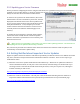
USER GUIDE 5.3 Configuring with the Windows Software The manual focuses primarily on configuring the Vector using the stick menus, but the concepts are the same for the software. Generally, the Vector can be more quickly and easily configured with the software, especially for first time users. However, both methods have been made as straightforward as possible. To configure with the Software, follow these high level steps.
USER GUIDE 9) With the Vector and the model perfectly level, record flat level mounting by clicking the “Record Flat Level” button. Now, the artificial horizon (AHI) display should show level, and should closely follow your movements as you pitch and roll the model. If the AHI is moving sluggishly and not keeping up with your movements, or is rotating on its own, DON’T FLY and contact support. 10) Configure sensors and the compass by clicking the “Configure Compass” button.
USER GUIDE IMPORTANT: follow these instructions carefully. If you make a mistake, it may be impossible to continue with stick menu configuration, since the Vector menus cannot be accessed unless the Vector knows the mappings for the Mode switch and the control stick.
USER GUIDE This should initiate menu mode, and the Main Menu should appear. To navigate menus, the elevator stick is used to scroll up and down the menu list. The aileron stick is used to select or deselect a menu item. When a menu item is selected, the elevator stick is used to increase or decrease the value of the parameter being changed.
USER GUIDE Whenever the airframe type is changed, many settings, such as controller gains, receiver settings, compass calibration, RTH settings, mode switch mappings, and any other airframe specific settings may be changed to their default values for that airframe type. So, remember to change the airframe type first, before making other settings.
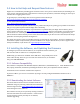
USER GUIDE Next, invoke menu mode, select the “Run Receiver Analysis Wizard” menu item under the “New Airframe Checklist” menu, and follow the instructions below: Wizard Prompt DISCONNECT MOTOR/Toggle Mode What to Do Make sure your motor(s) or propeller(s) are disabled, and toggle the Mode switch up and down to continue. During the wizard, the Vector shuts off the Vector throttle output channel for fixed wing, and all the Vector output channels for multirotors.
USER GUIDE 5.9 Configuring Auxiliary Receiver Inputs and Servo Outputs The Vector lets you configure several different auxiliary inputs (for transmitter mixed second aileron and other secondary control surfaces) and for additional Vector control inputs. Also, for fixed wing models, the Vector lets you configure up to two auxiliary servo outputs, for secondary servos. 5.9.1 Configuring the Auxiliary Input Channel (for non-serial Rx inputs) For serial Rx modes (SPPM and S.
USER GUIDE 5.10 Flight Modes, and Configuring the Mode/Submode Switches 5.10.1 Flight Mode Description The Vector supports a wide variety of flight modes, which you can select in flight using your Mode switch, and optionally a Submode switch. The table below describes these modes, and also indicates whether the GPS (with a good 3D fix) and the magnetic compass are required. The fallback flight mode is listed for when either the GPS or Compass is deemed untrustworthy.
USER GUIDE Stabilization Off Off N/A Turns off the stabilizer Cartesian Car Same as 2D Mode with Hold, except that the heading of the multirotor is remembered when you arm, and the stick always controls the multirotor as if it were yawed to that same heading. Not recommended for FPV flying. (see figure below) (Compass required) N/A Cartesian with Loiter C+L Same as Cartesian, but holds horizontal position using GPS when control stick is centered.
USER GUIDE 5.10.2 Control Stick Function in Multirotor Modes The figure below shows the behavior of the multirotor when the control stick is moved, for the presently selected flight mode. 5.10.3 2D Hold Flight Mode Information for Fixed Wing When 2D Hold flight mode is selected for fixed wing, both heading hold and altitude hold will be enabled. Heading hold uses the ailerons or elevons to hold the present heading, and altitude hold uses the elevator.
USER GUIDE designation in the table below. To configure the Mode switch positions, navigate to the “New Airframe Checklist”, and select the “Set up Mode/Submode Switches” menu item. Then, select the function of each of the up to 3 Mode switch positions. Your switch positions may be reversed from the illustration, depending on your radio settings. The following chart lists the modes that can be programmed for each of the 2 or 3 Mode switch positions (see section 5.9.
USER GUIDE The following chart lists the modes that can be programmed for each of the 2 or 3 Submode switch positions (see section 5.9.
USER GUIDE gains work is required in most circumstances. Basic Gains There are four main axes (or directions) that are controlled by separate gains: pitch, roll, yaw, and altitude hold (vertical). The gains that control these are referred to as “Basic Gains”. The basic gains control how strongly the Vector responds to perturbations (stick movements, air turbulence, etc.) in each axis.
USER GUIDE Roll Basic Oscillation/Vibration in Roll Axis Same Slow leveling in Roll axis when stick centered Same Yaw Basic Aggressive, sharp movements when yawing, pitch and roll oscillation/vibration The model may “fish-tail” or oscillate through the air Yaw drift Same, but only in 3D + Heading Hold Mode.
USER GUIDE For multirotors, the knob will adjust the gains from 50% to 200% of their default values. To see the present settings for these gains, navigate to the Stabilizer Settings menu item, and observe the values displayed. Values that are mapped to the knob will change in real time on the menu screen. The basic gain settings(s) are remembered each time you rotate the gain knob. If the gain knob is later disconnected or disabled, the remembered settings are still used. 5.11.1.
USER GUIDE 5.11.2 Verifying Correct Control Surfaces Movement (Fixed Wing) In addition to making sure that your radio sticks move the control surfaces in the correct direction, you also must ensure that the Vector’s stabilizer moves the surfaces in the right direction to keep the model in level flight. To make sure the stabilizer is correctly moving the control surfaces, first select either a 2D or 3D flight mode. If you are using a gain knob, make sure the gain is turned up enough to have an effect.
USER GUIDE 5.11.4 Arming and Disarming your Multirotor (Multirotor only) 5.11.4.1 Arm and Disarm Gestures The multirotor is armed by moving the throttle stick to the off position and holding the rudder stick in the rightmost position for 2 to 3 seconds, until the props spin continuously. For Mode 2 radios, this is done by simply holding the left (rudder/throttle) stick in the lower right-hand corner (the ARM corner) for approximately 1 second.
USER GUIDE Throttling up if the low battery auto-land feature has been triggered (the multirotor will arm in this condition). Arming if a controller error was detected during Vector boot-up. Arming if the Vector has not been fully configured. Arming if USB is connected. 5.11.5 Setting Idle Throttle (Multirotor only) When the multirotor is armed and the multirotor is level, the motors are commanded to spin at the idle throttle setting.
USER GUIDE Also, when you install propellers, make sure that you have selected a propeller of the correct orientation for the direction the motor is spinning. Make sure you have correctly set up your motor order, directions and propeller orientations before arming the multirotor with propellers! The multirotor may flip over violently or fly away uncontrollably if these are wrong! 5.11.
USER GUIDE 5.12 Configuring Return to Home and other Safety Modes The Return to Home feature (RTH), when configured properly, can return your model to the “home point” if your radio link is lost (in failsafe). Additionally, the Vector lets you program the maximum distance and maximum altitude that your model should never exceed.
USER GUIDE that the receiver is in failsafe. To do this, first select the "Thr Fsafe" option for “Failsafe Detection Method” in the menu. Then, program your receiver failsafes (following your radio manufacturer’s instructions) with your throttle trim all the way down, as shown in the left part of the illustration. Next, trim your throttle back up to a higher position. During normal operation, you must keep your throttle trim well above the failsafe setting, as shown in the right part of the illustration.
USER GUIDE 5.12.2 Configuring RTH/Safety Mode 5.12.2.1 Selecting the Desired Safety Mode The Vector has a few options for what to do when failsafe is detected, referred to as “Safety Modes.” To select the desired failsafe option, invoke the “Safety Configuration Menu” and change the “Select the Desired Safety Mode” item.
USER GUIDE This is not recommended for line of sight flying, since the multirotor will likely be pointing in a different direction than when you last had control over it, which can be confusing for line of sight. Advanced Return to Home Options: There are several advanced options that can be configured for RTH, under the “Advanced Setup…” menu. These are described in the Advanced Features section in the document. 5.12.
USER GUIDE Multirotor is armed, but an error has been detected. Check the OSD notification area to determine the cause of the error. Multirotor is armed. A 2D Flight Mode is selected A 3D flight mode (including ‘gyro mode’) is selected A Loiter flight mode is selected USB mode is active 5.14 Configuring the OSD The Vector’s built-in color OSD has many advanced features and display options. Even so, it can be easily configured to display basic information that is sufficient for most pilots.
USER GUIDE If the OSD information is too wide for your screen, select Narrow Screen Mode. If you have trouble reading the text, try changing the black level, or changing the colors of the text, as described below. To change color settings, select the “Color Setup” menu. You can change the color brightness, intensity, and hue in this menu. Also, you can select which colors to use for text and graphics.
USER GUIDE 5.14.4.2 Altitude, Speed and Distance Readouts Barometric Altitude: This displays the present barometric altitude of the model from the built in pressure sensor, which is zero referenced (set to zero) when the Vector is powered up. GPS Altitude: This displays the present GPS provided altitude, assuming there is a 3D GPS fix. This is also set to zero at power up.
USER GUIDE Never: GPS position is never displayed Trouble: GPS position is displayed when radio failsafe is detected, if RTH is triggered, or if an alarm has been triggered. Low Alt: GPS position is displayed for Trouble, and additionally will display if the present altitude is less than 100 feet/30meters. Distance: GPS position is displayed for Trouble, Low Alt, and additionally if the distance of the model from home exceeds the “RADAR Maximum Radius” menu item in the “Graphics and Indicators Setup” menu.
USER GUIDE There are two modes of RADAR operation: Home Centered Mode: The circular indicator in the center of the screen (Home/Center Screen marker) marks the home point, in a "bird's eye" view map. The RADAR location and direction of travel indicator (the chevron) indicates where the model is in relation to home. As your model moves relative to home, the chevron moves relative to the center of the screen.
USER GUIDE 5.14.6.6 Motor Battery Gauge The motor battery gauge graphically shows the main pack’s remaining mAH. Note that the total mAH must be set correctly for this feature to be accurate. 5.14.6.7 Home/Center Screen Marker Places a small circle with “T” in the center of the screen. 5.14.6.8 Flight Mode Indicator This indicator displays a 2 or 3 digit code for the flight mode presently being used. See the “Flight Mode Indicator” column in the table in section 5.9.
USER GUIDE To be able to see when an alarm has triggered, you must have the numeric readout for it displayed, so that you can see it flash. 5.14.7.1 Low Pack Voltage Alarm The alarm for pack voltage is set by specifying the per cell voltage that will trigger the alarm. The Vector automatically detects the cell count for your pack, so you can switch between packs of different cell counts, without needing to reset the alarm each time. 5.14.7.
USER GUIDE 5.15.2 Calibrating the Compass Compass calibration should be done with the model away from electrical fields and metal objects. The best place to calibrate the compass is outdoors, at the field where you will be flying. 5.15.2.1 Steps before Calibrating Before calibrating the compass, make sure that the compass is installed correctly, and that all equipment you plan to fly with, including cameras, canopies, etc., are fully installed on the model, and turned on.
USER GUIDE 5.15.2.3 Calibrating using the Mode Switch For your convenience, you can calibrate the compass without using your video display, as follows: Toggle mode switch 7 times – the Vector’s LED should flash a fast RED/GREEN Follow steps 2-6 above. The LEDs should now return to normal, indicating that the compass calibration is complete After calibration completes, verify proper compass operation as described in the “Testing the Compass” section below. 5.15.3 Testing the Compass 5.15.3.
USER GUIDE Four Channel A/V Distribution - The EagleEyes has four buffered video/audio outputs for connecting multiple sets of goggles and monitors at the same time. PowerPanel LCD Display support – When the optional PowerPanel™ LCD display is connected to the EagleEyes, the model’s present GPS position is automatically displayed via the Vector telemetry. With the LCD, the last known GPS position is remembered and displayed, in case you lose contact with your model.
USER GUIDE 6.2 First Flight Recommendations 6.2.1 Ground Tests before First Flight 6.2.1.1 Vibration Check for Fixed Wing If you can do so safely, it is recommended that you perform a prop-on engine run-up on the ground with 2D stabilization enabled (and the gain knob at midpoint or higher, if used), while watching your control surfaces for drift. This is especially important to do if you have a nitro, gas, or other high vibration motor.
USER GUIDE 6.3.1 Multirotor in-air leveling Slight adjustments to multirotor level offset can be corrected as follows: while hovering in a non-GPS 2D flight mode (2D or 2D with Altitude Hold, but NOT Center Stick mode), and when there is no wind, adjust your aileron and elevator radio trims so that the multirotor is hovering in a stationary position. Then, land the multirotor, disarm, and toggle the mode switch 5 times. At this point your level trims have been saved.
USER GUIDE 6.4.2 RTH Ground Testing If RTH is configured correctly, after your GPS as acquired a fix and the home position is set, when you turn your transmitter off (ON THE GROUND) the “RTH Engaged…” message should appear in the OSD notification area of the video screen. Additionally, the Flight Mode Indicator on the video screen should change to “RTH”. If you don’t see BOTH these notifications, RTH will not activate in the event of a receiver failsafe.
USER GUIDE Here is a description of this menu: Readout Name: When this item is highlighted, moving the aileron stick left and right lets you select the readout you want to modify. Once you have selected the desired readout, move the elevator stick down to move to the next menu items. See section 10 for a description of all readouts. Set Up Gauge/Swatch: This brings up the Gauge and Swatch Setup menu, described below.
USER GUIDE Speak Readout's Units?: If you have enabled this readout to be spoken either on alarm, or periodically, setting this item to “Yes” will result in the readout’s units (if applicable) to also be spoken. For example “Altitude 2-8-8-6 Feet”. Display Readout's Units?: If this item is set to “Yes”, the units of the readout (if any) will be displayed to the right of the readout. 7.1.
USER GUIDE Gauge/Swatch BEST Value: Here, you enter numeric value of the readout that you want to always display the green color. If a lower number is better for the readout, such as with altitude, you would enter the lowest value here. If a higher number is better, such as with voltages, you would enter the highest number here. Please see the examples at right. For the “Transmitter Voltage” readout, the best value is set to 12.60 and the worst is 10.80. The gauge will be green and show full at 12.
USER GUIDE the housing, as shown below. Temp Sensor BEFORE Modification Temp Sensor AFTER Modification 7.2.2 Brushless RPM Sensor 7.2.2.1 Brushless RPM Sensor Setup Assuming the Aux1/M5/RPM Vector port is not being used to control a servo or motor output, you can connect a MODIFIED Eagle Tree “Brushless RPM Sensor” (P/N RPM-BRS-V2) to that port, and display and log RPM. DO NOT connect an Optical or Hall (Magnetic) RPM sensor to the Vector! It could be damaged if you do.
USER GUIDE 7.3 Waypoints The Vector supports up to 26 waypoints. The Vector displays the Waypoints graphically on the OSD screen, making it easy for you to fly to them manually. At this time, the Vector will not autonomously fly to waypoints. 7.3.1 Configuring Waypoints Waypoints are configured in the software, by selecting the “GPS Waypoints Setup” tab. Internet connection is required to configure waypoints.
USER GUIDE 7.4 Data Logging Your Vector has a powerful built in Flight Data Recorder, which logs a large number of flight parameters and notification messages. Having data from your flight can take the guesswork out of troubleshooting in-flight issues, as well as keeping a record of your flights for later enjoyment. The logged data can be downloaded with the software, and viewed with our charting utility or with Google Maps. 7.4.
USER GUIDE 7.4.2.3 Viewing Flight Notifications After downloading data, you can view the notification messages and warnings that appeared on the OSD screen during flight. To do this, click on the “View Flight Notifications” button. See section 9 for the meanings of flight notification messages. 7.4.2.4 Sessions Each time you power on the Vector, a new “Session” is created in the data log. This makes it easy to differentiate data between different flights.
USER GUIDE Several additional advanced features for data logging and telemetry are available. These features include: o) Exporting flight data to Google Earth™ or Google Tracks™ p) Playing back data files with gauges and instruments q) Displaying live telemetry data from the EagleEyes™ FPV Station, either numerically, via Google Earth™, or on the chart. To access these features, check the “Show Advanced Telemetry Page” checkbox on the “Eagle Eyes and Data Logging” tab in the software.
USER GUIDE 7.5.2 Other Advanced RTH Settings 7.5.2.1 Minimum Speed for RTH The “Minimum Ground Spd (0 disable)” menu item is useful if you are flying in windy areas, and RTH could be triggered downwind. If your model is returning to home at a speed lower than specified ground speed, RTH will use your 'Climb' throttle setting instead of the 'Cruise' throttle setting to attempt to increase your RTH speed. 7.5.2.
USER GUIDE Vario Averager Seconds: This setting controls the averaging period of the variometer, in 10ths of a second units. For faster response, lower periods are recommended, but in rougher air longer periods may be required to avoid false alarms. Vario Minimum Sinkrate (Deadband): This setting controls the minimum sinkrate. Normally, this would be set to the standard sinkrate of your model, i.e., the rate at which it descends in smooth air with no thermals.
USER GUIDE If your current sensor’s true offset is 300mA, and the current offset is set to 0.3 in the menu, the Vector will always read 0.3 amps when the current draw is less than or equal 0.3 amps, but when the current climbs above 0.3 amps, the Vector will correctly read that current. If your amp meter shows that you are drawing greater than 0.3 amps when your motor is not running (due to your video camera, video transmitter, the Vector, and other accessories), but the Vector is reading 0.
USER GUIDE Additionally, for multirotors these criteria must be met at all times for GPS flight modes (loiter, etc.) to be enabled. For multirotors, allowing for a worse than the factory default GPS signal to be used increases the likelihood of problems during GPS flight modes, such as large amounts of sudden drift during loiter! Set Minimum Satellite Count: This lets you set the minimum number of satellites that must be in view.
USER GUIDE 8 Troubleshooting Issue My multirotor does not hold horizontal position well in the Loiter flight modes Solutions If you are using a high power video transmitter (especially 1.3GHz), try hovering with your video transmitter turned off to see if the issue goes away. If the transmitter is the cause, see the GPS Fix troubleshooting section below. Make sure your GPS module is getting an unobstructed view of the sky. Make sure your compass is calibrated correctly.
USER GUIDE "5.11.4 Arming and Disarming your Multirotor (Multirotor only)", specifically, you only move the throttle/rudder stick and must leave the elevator/aileron stick centered.
USER GUIDE and vice versa. It’s recommended you only change this setting after failing to fix the problem by adjusting the “Maximum Roll for RTH/Loiter” or if increasing that setting could create a stall risk for your airframe. Adjust this setting in about 10% increments. RTH: My model pitches or rolls (banks) too sharply or too shallowly during RTH.
USER GUIDE location of text on the screen. Try increasing or decreasing the “Black Level” setting in the OSD Setup menu. Increase the “Color Brightness” in the Color Setup menu. If a particular color is hard to read, either set intensity of that color to “High”, or change your settings to not use that color, in the Color Setup menu. Select “White” for “Numeric Parameters Color” in the Color Setup menu.
USER GUIDE 9 Notification Messages During boot-up and normal operation, the Vector constantly checks its status and settings, and the status of any connected accessories. If an issue is detected, the Vector will display a message in the OSD notification area either temporarily or until the issue is resolved, depending on the importance of the message. The table below describes these messages, and what they mean. Note that it is unlikely you will ever see most of these messages.
USER GUIDE This message is displayed if an error has occurred with the optional altimeter calibration step. If you try to arm when the Vector is in RTH mode (normally because the mode/submode switches are set to “RTH Test”), this message will Can't arm when RTH triggered! appear. Calibration error- see manual Can't change when knob used! The controller gains cannot be changed in the menus when the gain knob is enabled for that gain.
USER GUIDE External bus error! Flight Battery Not Detected Flip crash detected! Disarmed Flyaway detected-Disarming! Freefall detected!!! Gain Knob used but undetected GPS Status: Awaiting first fix GPS Status: Awaiting 3D fix GPS Status: Awaiting Enough Sats GPS Status: Awaiting HDOP Accuracy GPS Status: Post-Fix Countdown GPS Not Connected! GPS Fix Lost! GPS/Compass has old Firmware! Gyro not detected! Home Waypoint too far away! Idle throttle being reduced! Impact Detected! Kill Switch Activated!! Lan
USER GUIDE Loiter Off - Poor GPS or Mag Low Battery Voltage Detected! Magnetometer not detected! Maximum Altitude Exceeded! Maximum Distance Exceeded! Memory malfunction detected! Menus disabled during flight! Mode Switch not detected Motor Kill Input not Detected Moving or gyro decalibrated! Multirotor is ARMED! Multi not level enough to arm Multirotor is DISARMED! Multirotor Stability Issue! Must enable gain knob first! Need non-GPS on Mode/Submode New Receiver Mode detected! No RTH! Mode Sw unprogrammed
USER GUIDE Outputs Off:bad Configuration Please arm in non-GPS mode! Please run RC Wizard! Power Brownout Detected! RTH Flyaway detectedLanding! RTH Engaged: Move sticks to cancel RTH Engaged: Too Many Rx Glitches RTH Engaged: Bad Rx Pulsewidths RTH Engaged: Rx Failsafe Detected Rudder Issue: Rerun Wizard! S-BUS Error Detected! Submode Input not Detected! Throttle Failsafe Incorrect! Throttle Issue: Rerun Wizard! Too much movement - aborting! USB Mode - Outputs Disabled Warning: Too much vibration The V
USER GUIDE 10 Description of Numeric Readouts The following numeric readouts can be configured for display. Some require optional hardware.
USER GUIDE 2nd Rudder Rx In % The measured pulsewidth at the Vector’s 2nd Rudder input, if used Aileron/M2 Output % The pulsewidth being sent to the Vector’s Aileron/M2 output (0% = 1 millisecond, 100% = 2 milliseconds) Elevator/M3 Output % The pulsewidth being sent to the Vector’s Elevator/M3 output Throttle/M4 Output % The pulsewidth being sent to the Vector’s Throttle/M4 output Rudder/M1 Output % The pulsewidth being sent to the Vector’s Rudder/M1 output Aux1/M5 Output % The pulsewidth being s
USER GUIDE Spektrum Ant L Fades “” Spektrum Ant R Fades “” Distance to Pilot The present horizontal distance between the home point and the model Line of Sight Distnc The present horizontal and vertical distance between the home point and model, calculated using the Pythagorean theorem Cumulative Distance The total distance traveled by the model since boot-up, in either miles or kilometers Home Arrow Indicates the direction the model is traveling, relative to the home point.
USER GUIDE 12 Limited Warranty Eagle Tree Systems, LLC, (ET) warrants to the original purchaser (the Purchaser) that the purchased product (the Product) will be free from defects in materials and workmanship for a period of one (1) year from the date of original purchase. This limited warranty is nontransferable.