
User Manual


USER GUIDE
72
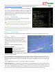
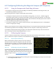
Model Centered Mode:
In this mode, an airplane icon placed in the center of the screen represents where the model is
presently, and an icon representing home is placed on the screen relative to the distance from home,
and the direction the model is flying relative to home. To return home, steer so that the home icon
is directly above the model on the screen (the model always points up).
Set the “RADAR Center Screen is...” menu item to “Model” for this mode.
In both RADAR modes, if you are using the magnetic compass, the compass is used to determine the
direction the model is facing. Otherwise, the GPS course reading is used.
RADAR Maximum Radius: This sets the maximum radius for the RADAR display. Set this to the maximum
distance away from home that you typically fly. For example, if you normally fly a maximum of 5000 feet away
from home in any direction, set this to 5000. If your model exceeds this distance, the RADAR icon will change
from normal video colors to reverse video colors, to indicate you are out of range.
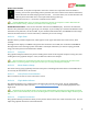
6.15.6.4 Flight Timer
The MicroVector provides a flight timer, which appears in the upper left-hand corner of the screen, when
enabled.
The Flight Timer display is in MM:SS until greater than 59 minutes is reached, then it switches to HH:MM:SS.
The flight timer starts counting up when the model is armed (for multirotors) or when it is flying (for fixed
wing). The timer pauses when disarmed or landed.
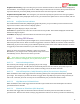
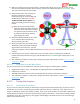
6.15.6.5 Compass
The graphical compass indicates the present heading of the model. If the magnetic compass is being used, that
reading drives the graphical compass. If not, the GPS course drives the compass.
Since movement is required for the GPS course to read accurately, the compass will be inaccurate if
your model is not moving relative to the ground, unless you are using the magnetic compass.
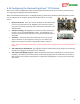
6.15.6.6 Motor Battery Gauge
The motor battery gauge graphically shows the main pack’s remaining mAH. Note that the total mAH must be
set correctly for this feature to be accurate.
6.15.6.7 Home/Center Screen Marker
Places a small circle with “T” in the center of the screen.
6.15.6.8 Flight Mode Indicator
This indicator displays a 2 or 3 digit code for the flight mode presently being used. See the “Flight Mode
Indicator” column in the table in section 6.11.1 – ‘Flight Mode Description’ for the code displayed with each
flight mode.
Normally the present flight mode is the one being commanded by the positions of the mode/submode
switches, but in some conditions, such as loss of GPS signal or receiver failsafe, a different flight mode may be in
use.
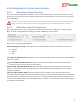
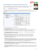
6.15.6.9 Graphical Variometer
The graphical charting variometer shows you the present climb or sinks rate, as well as historic rates. You can
adjust the graphical variometer as described below: