
User Manual

USER GUIDE
71
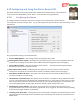
These advanced features are configured using the “Advanced Numeric Readouts…” menu. See section 8.2.1 –
‘The Advanced Numeric Readouts Menu’ for information on how to do this.
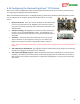
6.15.6 Graphics and Indicator Readouts
A variety of graphical and indicator readouts are available with
the MicroVector, which are configured under the “Graphics and
Indicators Setup” menu under the “OSD Setup” menu. Here is a
brief description of these:
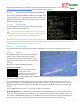
6.15.6.1 Speed Ladder
The speed ladder shows the present ground speed of the
aircraft, on the left side of the screen.
If the optional pitot airspeed sensor is connected, you
can display airspeed (instead of ground speed) on the ladder by
changing the “Use Pitot Spd for Ladder/RTH” setting.
Note that turning on the “Use Pitot..” setting causes the pitot to
be used to make sure that the model is flying when RTH is triggered, as well as for loiter control. So, the pitot
must be operating correctly for these features to work!
6.15.6.2 Altitude Ladder
The altitude ladder shows the present barometric altitude of the aircraft, on the right side of the screen.
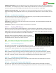
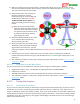
6.15.6.3 RADAR
The RADAR readout is an intuitive feature which
makes it easier to keep track of your model’s
location relative to home, and the direction your
model is traveling relative to the direction the pilot
is facing.
There are two modes of RADAR operation:
Home Centered Mode:
The circular indicator in the
center of the screen
(Home/Center Screen marker)
marks the home point, in a
"bird's eye" view map. The RADAR location and direction of travel indicator (the chevron) indicates where the
model is in relation to home.
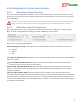
As your model moves relative to home, the chevron moves relative to the center of the screen. Also, the
direction the chevron is pointing indicates the direction the model is traveling, relative to home. So, if your
model is flying toward home, the chevron will point toward home, regardless of where it is on the display
screen.
Set the “RADAR Center Screen is...” menu item to “Home” for this mode.
Radar Up Direction: This parameter sets the UP direction of the RADAR feature, when in home centered
mode. For example, if you fly your model so that your body is facing 15 degrees N, you would set this to 15.
This results in the RADAR icon flying “up” on the MicroVector screen when you are flying the model in the
direction you are facing. Normally, the runway is perpendicular to the direction you are facing.