
User Manual

USER GUIDE
48
6.10 Configuring Auxiliary Receiver Inputs and Servo Outputs
The MicroVector lets you configure several different auxiliary inputs (for transmitter mixed second aileron and
other secondary control surfaces) and for additional MicroVector control inputs.
Also, for fixed wing models, the MicroVector lets you configure up to two auxiliary servo outputs, for
secondary servos.
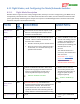
6.10.1 Configuring the Auxiliary Input Channel (for non-serial Rx inputs)
For serial Rx modes (satellite, SPPM and S.BUS™), these inputs are mapped automatically when the
Serial Rx Wizard was run, so this step can be skipped.
With parallel receiver mode (not serial receiver modes), you can configure the “Aux In” input of the receiver
harness to be one of the following:
Gain knob for adjusting the stabilizer gain in flight
Submode input for additional flight mode access
Flaps, Second Aileron, Elevator, or Rudder (with transmitter mixing).
Motor Kill switch
For the “High Perf Mini Quad” airframe type, the Aux In input must be mapped to the Motor Kill Switch.
To configure the input, navigate to the “New Airframe Checklist”, and select the “Set Up Aux Inputs/Outputs”
menu item. Then, select the “Aux Input Function(nonserial)” menu item and set the input as desired.
Remember to connect the Aux receiver harness input to the correct output on your receiver!
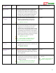
6.10.2 Configuring the MicroVector Auxiliary Output Channels (Fixed wing
only)
For fixed wing models, the MicroVector’s two auxiliary outputs can be configured for
Second Aileron, Elevator, and/or Second Rudder.
If you don’t have secondary control surfaces, or you selected a mixed secondary
channel in the “Tx Mixed Dual Contrl Surfaces” menu, you can skip this step.
If your transmitter does the mixing for these auxiliary channels, the appropriate inputs need to
be mapped as described above.
If you want the MicroVector to do the mixing for a Second Aileron output channel, do not select an input
corresponding to the Second Aileron input channel. Instead, just select the correct output as described below.
Note that Second Elevator and Second Rudder output channels require the radio to do the mixing for these
channels, and they must be mapped to the corresponding receiver input channel, as described above.
To configure the outputs, navigate to the “New Airframe Checklist”, and select the “Set Up Aux Inputs/Outputs”
menu item. Then, select the “Aux 1 Output Channel Functon” or “Aux 2 Output Channel Functon” menu item
and set the output as desired.
If you find that you need to have an output channel reversed, do that with the “Reverse Aux 1 Output?” or
“Reverse Aux 2 Output?” menu items.
For multirotors, the auxiliary output channels are set automatically, if needed.