
User Manual

USER GUIDE
36
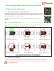
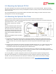
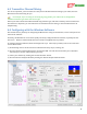
5.5 Controlling the MicroVector
The MicroVector is controlled and optionally configured with the following radio switch inputs:
5.5.1 The Mode Switch
The Mode switch (a 2, 3, or 5 position switch on your radio that is mapped to the “Mod” input of the receiver
harness, or mapped to an SPPM or S.BUS™ channel) is the primary way that you communicate with the
MicroVector via your radio.
Note that for most radios, 2 position radio switches will correspond to
mode/submode positions 1 and 5, and 3 position radio switches will correspond to
mode/submode positions 1, 3 and 5.
To take advantage of more than 3 positions on most radios, you will need to have
the radio mix multiple switches together. The PWM ranges for each mode/submode
switch position can be seen by hovering the mouse over the mode switch setup area in the software.
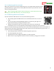
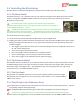
The mode switch serves two purposes:
1) The position of the switch determines the MicroVector’s present flight mode
2) Toggling the switch (rapid back and forth movement of the switch) invokes the MicroVector menu system,
letting you configure the MicroVector via your radio sticks, and performs other operations based on the
number of toggles:
One Toggle: switches OSD screens to the next screen (if multiple screens are configured), and serves as
an “OK” switch during menus
Two to Four Toggles: initiates menu mode
Five to Six Toggles: initiates the MicroVector leveling procedure.
Seven to Nine Toggles: starts the compass calibration procedure.
Ten or more Toggles: resets GPS home position (when not flying)
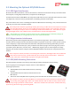
5.5.2 The Submode Switch
The Submode switch is an optional 2, 3 or 5 position switch on your radio (see above), which allows selection
of additional flight modes. This switch is useful if you need to utilize more than 5 flight modes, which is the
limit when using just the Mode switch. The Submode function can be mapped to the “Aux” input of the
receiver harness, or to an SPPM or S.BUS™ channel.
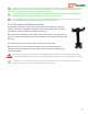
5.5.3 The Gain Knob
The gain knob is an optional control that can be used for adjusting stabilizer gains during flight.
The gain knob can be mapped to the “Aux” input of the receiver harness, or to a satellite, SPPM or
S.BUS™ serial channel.
5.5.4 The Kill Switch (for Multirotors Only)
The kill switch is an optional control for multirotors that can be used to instantly kill all motors. This can
be especially useful for initial flight testing.
For the High Perf Mini Quad airframe type, the kill switch is mandatory, and must be configured.
A momentary (spring loaded) switch can help reduce the likelihood of inadvertent triggering.
The kill switch can be mapped to the “Aux” input of the receiver harness, or to an SPPM or S.BUS™ channel.