
User Manual

USER GUIDE
30
4.8 Connecting the Optional GPS/Mag and other Accessories
4.8.1.1 The Bus Connector
The MicroVector’s “Bus” connector makes it easy to expand your MicroVector’s capabilities with additional
sensors. Bus sensors are “daisy chained” together, and can be connected in any order.
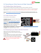
4.8.1.2 Hooking Up Bus Sensors
Each Bus sensor comes with a Bus wiring harness. Additional harnesses are available from Eagle Tree.
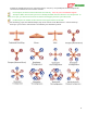
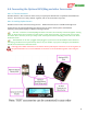
Connections to the optional GPS/Mag, Pitot Airspeed sensor, Alerter buzzer/LED*, and InfoPanel
telemetry/status/menu display are shown in the figure below.
The “Bus” connectors on the GPS/Mag and other accessories are internally connected together. Wiring
order, or which of the two connectors on each sensor is used, does not matter. In other words, you can plug
into either “Bus” connector, and if you “daisy-chain” the Airspeed with the GPS/Mag, either unit can be at the
head of the chain.
The InfoPanel can be “hot” plugged and unplugged. If you wish to use the InfoPanel either before or
after flying, and don’t wish to permanently mount it on your model. If you plan on doing this, the InfoPanel
should be connected at the end of the chain.
* The high power LEDs and buzzers in the Alerter Buzzer/LCD impose restrictions on the 5V regulator of
the optional ET PSU. Do not exceed 500mA current draw on the 5V ET PSU regulator when using the
Alerter!