
User Manual

USER GUIDE
26
4.7 Connecting Servos/ESCs to the MicroVector
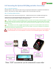
4.7.1 The ESC/Servo Connector
The ESC/Servo connector provides signal outputs to your ESC(s), and/or servos. Do not power your servos
via this connector! Servos must be powered by direct connection to the +/- terminals of your BEC, PDB,
battery, or other appropriate power source!
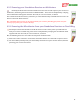
Normally the signal lines of your ESCs or servos will be soldered directly to the ESC/Servo connector lines,
after determining which connections go to which ESC or servo, and after cutting the lines to the correct lengths.
After soldering the connections, make sure you disconnect the ESC/Servo harness from the MicroVector before
proceeding to the configuration section.
Never connect the ESC/Servo harness to the MicroVector until you have verified the MicroVector
airframe type is correctly selected! If a fixed wing airframe type is selected with a multirotor, the
propellers can spin uncontrollably at high speed at power-up! Likewise, if a multrotor airframe type is
selected with fixed wing, the servos can be pushed beyond their endpoints and be destroyed!
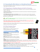
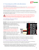
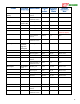
4.7.2 ESC/Servo Connector Pinout
The connector pinout is as follows:
M6/Aux2: Connects to ESC 6 signal line for hexacopters, or to an auxiliary servo signal line for fixed wing.
M5/Aux1: Connects to ESC 5 signal line for hexacopters, or to an auxiliary servo signal line for fixed wing.
M4/Throttle: Connects to ESC 4 signal line for
multirotors (except tricopter), to the yaw servo for
tricopters, or to the motor ESC or throttle servo signal
line for fixed wing.
5V Pwr: Typically not used. Note that all the “5V
Power” connections are connected together inside
the MicroVector. Don’t power servos from this
connection! Don’t connect a power source to more
than one of the 5V Pwr connections! 6V Max!
Ground: On multirotors, this line can be connected to
all the ESC signal ground wires, if desired. But, since
the ESC is already grounded through its negative
battery terminal, this additional ground connection may not be necessary unless the ESC has optical ground
isolation.
M3/Elv: Connects to ESC 3 signal line for multirotors, or the elevator servo signal line for fixed wing.
M2/Ail: Connects to ESC 2 signal line for multirotors, or the aileron servo signal line for fixed wing.
M1/Rud: Connects to ESC 1 signal line for multirotors, or the rudder servo signal line for fixed wing.
4.7.3 Correct Hookup of your ESC and/or Servo Signal Lines
This section helps you determine correct ESC/Servo harness signal line hookup, based on your model type.
Review this section carefully before cutting any wires or configuring your MicroVector.
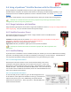
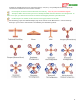
The figure below shows the supported airframe types. For each airframe, the arrow indicates the direction
of forward travel, which corresponds to the forward direction of the arrow on the MicroVector label when
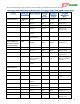
the MicroVector is mounted correctly. Determine which airframe matches yours, and refer to the
connection chart. For the multirotor airframe types, the numbers in the figure correspond to the motor