
User Manual

USER GUIDE
21
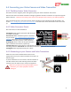
4.4 Connecting your Video Camera and Video Transmitter
4.4.1 The MicroVector Video Connector
The Video connector supplies power and signal to/from your video transmitter and camera.
Note that the camera and video transmitter voltages supplied to the Power connector are output through the
Video connector. Make sure that these power sources are adequate and correct for your video equipment.
Note also that the power to the camera and/or video transmitter can be switched on and off remotely. See
section 6.16 – ‘Configuring the Video Power Switches’ in the manual for more information on how to set this
up.
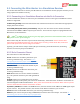
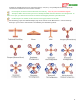
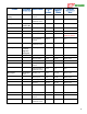
4.4.2 Video Connector Pinout
The connections are described below:
VTx Signal: Video signal output (with OSD overlay) to
your video transmitter
VTx Pwr Out: When transmitter power is switched
on (see section 6.16 – ‘Configuring the Video Power
Switches’), the voltage from the VTx Pwr In line of
the Power connector is present at this connection.
Ground (2x): These connect to the grounds of your
video transmitter and camera, respectively.
Cam Pwr Out: When camera power is switched on (see section 6.16 – ‘Configuring the Video Power Switches’),
the voltage from the Cam Pwr In line of the Power connector is present at this connection.
Cam Signal: Video signal input from your camera
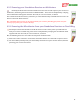
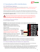
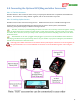
4.4.3 Connecting to your Camera and Video Transmitter
Solder the wires of the included video harness to the
appropriate wires of your video transmitter and camera, as
shown at right.
Or, male and female servo connectors could be installed on
the video harness wires and matching camera and video
transitter wires to make it easy to swap out equipment.
Make sure you have the wiring and voltages correct.
Otherwise, your video equipment could be
damaged!