
User Manual

USER GUIDE
17
4 MicroVector Wiring Harnesses
The MicroVector’s wire harnesses are shown below. Note that a set of replacement wire harnesses is available
(p/n VEC-CAB-SET). Having additional sets make it easier to move your MicroVector from model to model.
4.1 Included Wire Harnesses
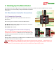
4.1.1 Wire Harness Overview
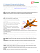
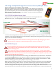
Five “pigtail” harnesses are included with
the MicroVector, as shown at the right.
You will need to solder each used wire to
the appropriate connection on your other
equipment, after cutting all leads to the
correct lengths for your model.
Make sure you use heatshrink or electrical tape to fully insulate the solder points!
Make sure to cap off or remove unused wires from the harnesses!
Note: If 3rd party wire harnesses are used with the MicroVector, the “projections” or “ears” will need to be
trimmed off the connectors, if the MicroVector case is installed. The projections can cause the plugs to not
fully insert when the case is used.
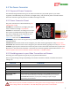
4.1.2 Harness Color Coding
The included harness wires are color coded as follows:
Yellow: A signal INPUT TO the MicroVector (eg., a receiver channel input)
White: A signal OUTPUT FROM the MicroVector (eg., an ESC output)
Orange: Low voltage (typically 5V, from your PDB or PSU)
Red: Potentially high voltage power into or out of the MicroVector (eg., 12V for your video transmitter)
Black: Ground