
User Manual


USER GUIDE
131
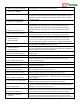
Aux2/M6 Output %
The pulsewidth being sent to the MicroVector’s Aux2/M6 output, if configured
G-Force X Axis
The g-force measured in the X axis
G-Force Y Axis
The g-force measured in the Y axis
G-Force Z Axis
The g-force measured in the Z (vertical) axis
Pitch
The amount of pitch from level, in degrees
Roll
The amount of roll from level, in degrees
Yaw
The amount of yaw motion, in degrees (When the compass is enabled and
properly calibrated, this represents the heading relative to true North)
Climbrate
The model’s present climbrate
Vario(TEC Climbrate)
The model’s present climbrate, after Total Energy Compensation has been applied
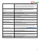
GPS Satellite Count
The number of satellites in view, as reported by the GPS
Receiver RSSI
The present RSSI %
GPS Groundspeed
The present ground speed of the model, as reported by the GPS
GPS Altitude
The zero referenced altitude, as reported by the GPS
GPS Course
The present true course heading, as reported by the GPS
GPS HDOP
The present HDOP, as reported by the GPS
Spektrum Rx Holds
Receiver health information from the Spektrum™ Flightlog™ data port. Find the
Spektrum™ Flightlog™ manual online for more information
Spektrum Lost Frames
“”
Spektrum Ant A Fades
“”
Spektrum Ant B Fades
“”
Spektrum Ant L Fades
“”
Spektrum Ant R Fades
“”
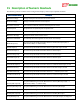
Distance to Pilot
The present horizontal distance between the home point and the model
Line of Sight Distnc
The present horizontal and vertical distance between the home point and model,
calculated using the Pythagorean theorem
Cumulative Distance
The total distance traveled by the model since boot-up, in either miles or
kilometers
Home Arrow
Indicates the direction the model is traveling, relative to the home point. An up