
User Manual

USER GUIDE
112
12.4.5 The Command Table
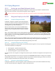
12.4.5.1 Adding Commands to the Table
Waypoint commands are added to the command table clicking the “Insert Command” button, or clicking on the
map. To add a command at a specific point in the table, click the Index field of the waypoint preceding the
insertion point, then click the “Insert Command” button.
12.4.5.2 Changing the Command Type
Click on the “Cmd Type” table column for the new command, to change the command type, if necessary.
Commands are added initially as type “Waypoint.”
12.4.5.3 Changing Command Order in the Table
Commands can be reordered in the table by clicking and dragging the Command Index number.
12.4.6 Command and Parameter Reference
The information below describes the available commands, and available options for each supported command.
Note that most navigation commands will result in both horizontal and vertical navigation, which will
occur even at ground level if the “Permit Low Altitude Waypoints” option is enabled!
12.4.6.1 Waypoint Command
The Waypoint command causes the system to navigate to the specified position (latitude, longitude and
altitude).
When the MicroVector begins navigation to a waypoint, the message “Navigating to Waypoint X” will appear
briefly in the OSD notification area, where X represents the waypoint index.
Parameters:
Lat: The Lat field specifies the target latitude for the command, in DDD.DDDDD format. A positive value
represents North, and negative represents South.
Lon: The Lon field specifies the target longitude for the command, in DDD.DDDDD format. A positive value
represents East, and negative represents West.
Alt: The Alt field specifies the target altitude for the command. The target altitude must be above about 60
feet (18 meters), unless the 'Permit Low Altitude Waypoints' is enabled.
Yaw: (multirotor) The Yaw field specifies the direction the multirotor should face when navigating to the
specified location. This field is ignored if there is an active ROI command. Values are in degrees, clockwise
is positive. (East = 90.0, West = 270.0, etc)
Radius: (fixed wing) The Radius field specifies the circling radius to use, if loitering is necessary. If set to
“0,” and loitering is not necessary, the model will fly straight through the target point before loading the
next waypoint command. If set to “0” and loitering is necessary, the “RTH/Loiter Circle Radius” will be
used instead. A positive radius indicates clockwise rotation, and a negative radius indicates a counter-
clockwise rotation.
12.4.6.2 Delay Command
The Delay command causes the model to loiter at its present position, for the specified number of seconds.
Normally, Delay commands are added immediately after waypoint commands, to cause the model to loiter at
that waypoint’s position.