USER GUIDE MicroVector Multirotor/Fixed Wing Flight Controller + OSD User Guide December, 2016 Version 1.0 Software Version 12.
USER GUIDE Table of Contents Contents 1 Safety ............................................................................................................................................................................. 8 1.1 .... Read the Manual!................................................................................................................................................................8 1.2 .... Special Symbols used in the Manual .........................................................
USER GUIDE 4.4.3 Connecting to your Camera and Video Transmitter ................................................................................................ 21 4.5 .... Connecting the MicroVector to a Standalone Receiver ................................................................................. 22 4.5.1 Connecting to a Standalone Receiver via the Rx In Connector ............................................................................ 22 4.5.2 Rx In Connector Pinout .........................
USER GUIDE 6.5.1 Teaching the MicroVector about Spektrum™ Satellite, SPPM or S.BUS™ Radio Channel Mappings ... 41 6.5.2 Navigating the Stick Menus ................................................................................................................................................. 43 6.5.3 Exiting Menu Mode ................................................................................................................................................................. 43 6.5.
USER GUIDE 6.15.2 Setting Display Units (English or Metric) .............................................................................................................. 68 6.15.3 Choosing what to Display on the OSD Screen ...................................................................................................... 69 6.15.4 Basic Numeric Readouts ................................................................................................................................................
USER GUIDE 8.1.2 Initial Tuning ............................................................................................................................................................................. 86 8.1.3 PID Tuning .................................................................................................................................................................................. 87 8.1.4 Other Pro Tips ...................................................................................
USER GUIDE 12.4.1 Waypoint Related Settings on the Waypoint/Nav Setup Tab .................................................................... 107 12.4.2 The Waypoint Setup Tab ............................................................................................................................................ 109 12.4.3 Using the Waypoint Map ............................................................................................................................................ 110 12.4.
USER GUIDE 1 Safety The MicroVector is intended to be used exclusively for recreational purposes in model aircraft. Using the MicroVector for other purposes is not supported. Further, using the MicroVector in situations where its use or failure could result in loss of life, bodily injury or property damage is expressly prohibited. Eagle Tree Systems, LLC, is not responsible for your use of this product, or for any damages or injuries you may cause or sustain as a result of its usage. 1.
USER GUIDE Never connect ESCs or servos to the MicroVector until you have verified the airframe type is correctly selected! Doing so can cause multirotor propellers to spin at high speed, or can destroy fixed wing servos.
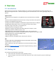
USER GUIDE 2 Overview 2.
USER GUIDE 2.3 Specifications Supported Airframes: o o High Perf Mini Quad, Quadcopter, Tricopter, and Hexacopter multirotors Traditional fixed wing, Elevon, and V-tail planes Recommended Airframes: The MicroVector is recommended for small/light airframes only: o 300mm (12”) or smaller multirotors o 800mm (32”) or smaller wingspan planes. Consider using the Vector for larger models.
USER GUIDE 2.5 Installing the Software, and Updating the Firmware To configure your MicroVector with the software, or to update the MicroVector firmware, you will need to install our software on a compatible device. Additionally, you will need a standard “micro” USB cable. You probably have one of these cables already, but if not, you can order one online from us, or elsewhere. Our p/n is USBCAB-MICRO. 2.5.1 Software Compatibility The software is compatible with Windows™ 10, Windows™ 8/8.
USER GUIDE Also, note that if you install new software and it detects that the MicroVector’s firmware needs an update, it will automatically run the firmware update utility. 2.6 Getting Notified about Important MicroVector Updates Eagle Tree updates the MicroVector firmware and software periodically to add new features or to address issues that may arise, and will issue important hardware information bulletins as needed.
USER GUIDE 2.7 Glossary of Terms used in the Manual Here are definitions for some of the terms used throughout the manual. FPV – FPV stands for First Person View. If you are not familiar with FPV, there are many websites devoted to it. Our FPV overview web page at http://www.eagletreesystems.com/OSD has a brief tutorial on FPV, which is a good place to start. OSD – OSD stands for On Screen Display. The OSD shows flight information, overlaid on the video camera image. RTH – Return to Home.
USER GUIDE Control Surfaces – Your model’s elevator, ailerons (or elevons), flaperons, and/or rudder (if equipped). Mode Switch – A two or three position switch on your radio transmitter which you have configured to control the “Mod” input on the MicroVector’s Receiver Connection Harness. Toggle – One fairly rapid movement the Mode Switch between its extents. (UP/DOWN or DOWN/UP) Configuration Gestures – A series of toggles of the Mode Switch.
USER GUIDE 3 Hooking Up the MicroVector This section describes the MicroVector’s cabling and connections, and how to connect the MicroVector to your RC receiver, your servos or ESCs, and your FPV video transmitter and camera. 3.1 MicroVector Controller Connections 3.1.1 Connection Overview The figure at right shows all the possible connections to the MicroVector. There are 3 types of connectors used on the MicroVector: JST “SH”: ESC/Servo, Rx In, UART, Video, and Power connectors.
USER GUIDE 4 MicroVector Wiring Harnesses The MicroVector’s wire harnesses are shown below. Note that a set of replacement wire harnesses is available (p/n VEC-CAB-SET). Having additional sets make it easier to move your MicroVector from model to model. 4.1 Included Wire Harnesses 4.1.1 Wire Harness Overview Five “pigtail” harnesses are included with the MicroVector, as shown at the right.
USER GUIDE 4.2 The Power Connector 4.2.1 Purpose of Power Connector For both fixed wing and multirotor types, the Power connector lets you provide power to your video equipment, and additionally lets you monitor your flight battery, and provide 5V power to the MicroVector. The Power connector typically connects to a PDB, or the Eagle Tree PSU. 4.2.
USER GUIDE 4.3 Using the Optional Eagle Tree Current Sensor/PSU (ET PSU) (skip this section if you are not going to use the ET PSU) Eagle Tree’s high efficiency and low noise PSU accepts up to 6S voltage input, and provides filtered 5V and up to 12V output at 1A max per channel*. It's perfect for powering most FPV gear, and can also power your receiver on multirotors (when NO servos are being powered by the RX!), eliminating the need for an external BEC.
USER GUIDE need a boost when operating at the lower end of 3S, a boost regulator can easily be spliced into the MicroVector's video harness. 4.3.3 ET PSU Current Sensor Maximum Continuous Current, and Load Testing The PSU current sensor’s continuous current capability depends on the type of connectors/wires you are using, and other factors.
USER GUIDE 4.4 Connecting your Video Camera and Video Transmitter 4.4.1 The MicroVector Video Connector The Video connector supplies power and signal to/from your video transmitter and camera. Note that the camera and video transmitter voltages supplied to the Power connector are output through the Video connector. Make sure that these power sources are adequate and correct for your video equipment. Note also that the power to the camera and/or video transmitter can be switched on and off remotely.
USER GUIDE 4.5 Connecting the MicroVector to a Standalone Receiver This section describes how to connect your MicroVector to a standalone receiver (skip this section if you are using a Spektrum™ satellite receiver). 4.5.1 Connecting to a Standalone Receiver via the Rx In Connector Use the included Rx In harness to connect to your standalone receiver.
USER GUIDE 4.5.3 Powering your Standalone Receiver on Multirotors Normally the black and red leads on the Rx In harness can be used to power your receiver on multirotors, eliminating the need to have an additional BEC. This can be accomplished by crimping the red and black leads together with the “Ail” lead, on a servo connector, as shown. The red lead on the Rx In harness (“5V Power”) is connected internally in the MicroVector to the “5V Power” lead on the Power harness.
USER GUIDE 4.6 Using a Spektrum™ Satellite Receiver with the MicroVector Using a Spektrum™ compatible satellite receiver is quite simple with the MicroVector. The MicroVector will power the satellite, and has built-in “bind plug” and GUI binding capability, so you normally don’t need a standalone Spektrum™ receiver to bind the satellite. See section 4.6.3 – ‘Satellite Binding’. Also, built in wizards make it easy to teach the MicroVector about your satellite channel assignments.
USER GUIDE 4.6.3.3 After Binding is Initiated After initiating binding via one of the above methods, your bind LED should now be blinking. Now, bind your transmitter as you normally would. If binding fails for some reason, wait for the MicroVector to boot up, then simply cycle power. The MicroVector will automatically try the next bind method, and will cycle through all bind methods on each power cycle until you find one that works.
USER GUIDE 4.7 Connecting Servos/ESCs to the MicroVector 4.7.1 The ESC/Servo Connector The ESC/Servo connector provides signal outputs to your ESC(s), and/or servos.
USER GUIDE numbers on the MicroVector servo connector label (1 = M1, etc.). For quadcopters and hexacopters the curved arrows indicate the correct motor rotation. For tricopters, the motor rotation directions are arbitrary. Also, the yaw servo MUST be digital! Tricopter rudder control of the yaw servo is initially disabled when the throttle is at its off position. In order to test yaw, you will need to increase the throttle stick slightly with the system disarmed.
USER GUIDE The chart below shows typical receiver and servo/ESC connections for these airframe types. * The Receiver Output and MicroVector Rx Harness sections do not apply to Satellite, SPPM, S.BUS™ or receiver modes.
USER GUIDE Airframe MicroVector Airframe Type V-Tail with Ailerons (cont.
USER GUIDE 4.8 Connecting the Optional GPS/Mag and other Accessories 4.8.1.1 The Bus Connector The MicroVector’s “Bus” connector makes it easy to expand your MicroVector’s capabilities with additional sensors. Bus sensors are “daisy chained” together, and can be connected in any order. 4.8.1.2 Hooking Up Bus Sensors Each Bus sensor comes with a Bus wiring harness. Additional harnesses are available from Eagle Tree.
USER GUIDE 5 Mounting the MicroVector and Accessories 5.1 Mounting the MicroVector 5.1.1 Mounting Location and Orientation Mount the MicroVector flat and level with the top facing toward the sky and the red arrow on the MicroVector case (or the arrow on the MicroVector PC board) facing toward the nose of your model (the direction of forward travel). The MicroVector should be mounted as near to the model’s Center of Gravity (CG) as practical.
USER GUIDE 5.1.2.1 Mounting with Case Installed When cased, the best way to mount the MicroVector is to use double sided, closed cell (solid, gum like) foam tape. A great choice is Scotch/3M indoor-outdoor tape, model 411-DC, but there are many good options. When removing the MicroVector from mounting tape, twist the MicroVector rather than trying to pull the MicroVector up. It’s easier that way . 5.1.2.
USER GUIDE 5.2 Mounting the Optional GPS/MAG Sensor 5.2.1 GPS Signal Interference RF noise from video transmitters, cameras, other devices, and even increased solar activity can interfere with GPS reception, causing GPS position drift, or complete loss of GPS signal. It’s important to mount the GPS/MAG as far away from all RF noise sources as practical and to mount it so that it is higher than, and as far away as possible from, transmitting antennas on the model.
USER GUIDE The GPS/MAG must be flat relative to the MicroVector, if the compass is used. Mounting errors of even a few degrees in the pitch or roll axes can introduce noticeable error in the compass heading, leading to toilet bowl behavior in multirotors or inaccurate navigation in planes. The MicroVector automatically computes the magnetic declination (compass error) at your location, so it is normally not necessary to rotate the GPS/MAG to correct for compass error.
USER GUIDE 5.3 Mounting the Optional ET PSU The optional ET PSU can be mounted with double sided foam tape, or with other methods. Before mounting the Current Sensor/PSU, make sure that your ESC/Motor connector, battery connector and PSU to MicroVector harness will reach. It is recommended that the Current Sensor/PSU be mounted so that cooling air can flow into the one of the openings of the current sensor during flight. 5.
USER GUIDE 5.5 Controlling the MicroVector The MicroVector is controlled and optionally configured with the following radio switch inputs: 5.5.1 The Mode Switch The Mode switch (a 2, 3, or 5 position switch on your radio that is mapped to the “Mod” input of the receiver harness, or mapped to an SPPM or S.BUS™ channel) is the primary way that you communicate with the MicroVector via your radio.
USER GUIDE Note that the multirotor will rearm instantly when the kill switch is disengaged, until about 3 seconds after it’s engaged (in case the kill was accidental). Once 3 seconds have elapsed with the Kill Switch set, the multirotor is permanently disarmed until you rearm it. During RTH (including RTH test modes) the Gain Knob and Kill Switch inputs are disabled, to prevent inadvertant changes in these inputs due to loss of reliable Rx signal.
USER GUIDE 6 Configuring the MicroVector 6.1 Configuration Overview The MicroVector can be completely configured using either the onscreen (stick) menus, the optional InfoPanel display, or the Vector Windows Software (the software). At a high level, configuration consists of these steps: Configuring your radio to work with the MicroVector Teaching the MicroVector about your radio’s serial channel mapping, if you are using the satellite, SPPM or S.
USER GUIDE 6.3 Transmitter Channel Mixing For correct operation, you must make sure that you have disabled channel mixing in your radio, since the MicroVector does the mixing for you. For example, if you are using an elevon (flying wing) model, your radio must be configured for traditional airframe type rather than elevon type.
USER GUIDE 5) Make sure that the graphical indicators in the “Receiver Input Monitor and Switch Mapping” section move correctly as you move your radio sticks, switches, and/or knobs. The sliders representing the control surfaces should move proportionally with your control stick, and in the same direction. If they don’t, something is wrong – DON’T FLY until the issue is resolved! 6) Program the desired functions of your mode/submode switches using the dropdown menu items in the input monitor section.
USER GUIDE 6.5 Configuring the MicroVector via Stick Menus or InfoPanel This section describes configuring the MicroVector using the OSD stick menus (or the InfoPanel). This section assumes you have already configured your RC transmitter and bound it to your receiver, and connected your receiver and video display to the MicroVector, as these steps are required to do stick menu configuration. You do not need a camera or video transmitter to configure the MicroVector with the stick menus.
USER GUIDE If you are using a serial mode, the Wizard will ask you to follow a series of steps. These are detailed below. IMPORTANT: follow these instructions carefully. If you make a mistake, it may be impossible to continue with stick menu configuration, since the MicroVector menus cannot be accessed unless the MicroVector knows the mappings for the Mode switch and the control stick.
USER GUIDE 6.5.2 Navigating the Stick Menus Your MicroVector should now be configured so that you can access the stick menus. Now toggle your mode switch twice (two rapid, full movements between the switch’s extents, in less than 2 seconds). This should initiate menu mode, and the Main Menu should appear. To navigate menus, the elevator stick is used to scroll up and down the menu list. The aileron stick is used to select or deselect a menu item.
USER GUIDE 6.6 Selecting the Airframe type The next configuration step is to select the Airframe type. Please review the chart in section 4.7.3 - ‘Correct Hookup of your ESC and/or Servo Signal Lines’ to determine the airframe type you should select. Then, invoke menu mode, select the “Change Airframe Type...” menu item under the “New Model Checklist” menu, and follow the instructions.
USER GUIDE 6.7 Accepting the Airframe Type For safety, when you select the airframe type via the Stick Menus, the MicroVector will ask you to confirm the newly selected airframe type on the next boot-up after you change it, but only after USB is disconnected. The MicroVector’s outputs will not be turned on until you OK the airframe type. The message at right will appear on the screen during boot for about 30 seconds. Toggle the mode switch to accept the new type, if it’s correct. 6.
USER GUIDE 6.9 Running the Receiver Analysis Wizard The Receiver Analysis Wizard (the Wizard) learns about your radio stick directions and throws, the minimum and maximum RSSI output of your receiver, your receiver’s failsafe positions, and other information. it later. If you make a mistake when you run the wizard, just rerun Before running the Wizard, make sure that you have hooked up your RSSI (if used), turned off any radio mixing (except as described earlier), and set your radio trims as desired.
USER GUIDE high here than too low. This throttle setting will be used to gain altitude, compensate for high wind, or attempt to recover from a stall during RTH. For multirotors, move your throttle stick all the way up, and toggle Mode. Set throttle off/Toggle Mode Move your throttle stick all the way off, and toggle Mode. Wizard Done-Tog Mod to reboot The MicroVector has now learned your receiver settings.
USER GUIDE 6.10 Configuring Auxiliary Receiver Inputs and Servo Outputs The MicroVector lets you configure several different auxiliary inputs (for transmitter mixed second aileron and other secondary control surfaces) and for additional MicroVector control inputs. Also, for fixed wing models, the MicroVector lets you configure up to two auxiliary servo outputs, for secondary servos. 6.10.1 Configuring the Auxiliary Input Channel (for non-serial Rx inputs) For serial Rx modes (satellite, SPPM and S.
USER GUIDE 6.11 Flight Modes, and Configuring the Mode/Submode Switches 6.11.1 Flight Mode Description The MicroVector supports a wide variety of flight modes, which you can select in flight using your Mode switch, and optionally a Submode switch. The table below describes these modes, and also indicates whether the GPS (with a good 3D fix) and the magnetic compass are required. The fallback flight mode is listed for when either the GPS or Compass is deemed untrustworthy.
USER GUIDE Stabilization Off Off N/A Turns off the stabilizer Cartesian Car Same as 2D Mode with Hold, except that the heading of the multirotor is remembered when you arm, and the stick always controls the multirotor as if it were yawed to that same heading. Not recommended for FPV flying. (see figure below) (Compass required) N/A Cartesian with Loiter C+L Same as Cartesian, but holds horizontal position using GPS when control stick is centered.
USER GUIDE 6.11.2 Control Stick Function in Multirotor Modes The figure below shows the behavior of the multirotor when the control stick is moved, for the presently selected flight mode. 6.11.3 2D Hold Flight Mode Information for Fixed Wing When 2D Hold flight mode is selected for fixed wing, both heading hold and altitude hold will be enabled. Heading hold uses the ailerons or elevons to hold the present heading, and altitude hold uses the elevator.
USER GUIDE configured on the mode or submode switches. Non GPS flight modes, such as 2D and 3D, do not have the “(GPS)” designation in the table below. To configure the Mode switch positions, navigate to the “New Airframe Checklist”, and select the “Set up Mode/Submode Switches” menu item. Then, select the function of each of the up to 5 Mode switch positions. Your switch positions may be reversed from the illustration, depending on your radio settings.
USER GUIDE 6.11.5 Programming the Optional Submode Switch To configure the Submode switch positions, navigate to the “New Airframe Checklist” menu, and select the “Set up Mode/Submode Switches” menu item (see above). Then, select the function of each of the up to 5 Submode switch positions. The Submode switch is ONLY active when the Mode switch is set to the “2D + Submod” position. Your switch positions may be reversed from the illustration, depending on your radio.
USER GUIDE 6.
USER GUIDE If a gain value is excessively high for your airframe, the oscillations can make the model become uncontrollable! If the Vertical/Altitude gain is set too low, RTH may not work correctly! When you are in 3D Heading Hold (Direct Rate) mode, the basic gains dictate how strongly the controller will work to keep the model in its current orientation. Stabilizer Responsiveness The responsiveness control is applicable only in 2D (leveling) modes.
USER GUIDE However, airframe types vary widely, so the default gains may cause problems with your model. There are three ways to reduce the likelihood of gain related problems with your first flights: a) Set up a gain knob as described below, so you can control the gains of one or more axes quickly from your radio, during flight. To do this, you will need to map a knob from your transmitter, as described earlier in the manual.
USER GUIDE The basic gains act as a multiplier on top of the inner loop PID gains. For example, increasing the Pitch/Elevator Basic Gain has the effect of increasing each of the Inner P, I, and D pitch gains by the same proportion. Pitch and Roll: The “Maximum Pitch” and “Maximum Roll” angle settings control the maximum pitch and roll to which your model will be commanded by the controller, when in a 2D mode.
USER GUIDE Correct and Incorrect Control Surface Movement 6.12.3 Confirming ESC Endpoints are set Correctly (Multirotor only) For correct multirotor operation, all of your ESC endpoints must be set the same, so that the idle throttle setting causes each motor to spin at the same speed, and so that the full range of your throttle is utilized by the ESCs. Consult the manual for your ESCs to determine how to set endpoints, and set them all the same.
USER GUIDE If prefered, the pre-arming twitches can be disabled by selecting “Allow Fast Arming?” option in the “Advanced Multirotor” stick menu, or under “Other Advanced Settings” on the Flight Controller tab in the software. “Allow Fast Arming” is enabled by default when the High Perf Mini Quad airframe type is selected. The propellers will spin when the multirotor is armed.
USER GUIDE 6.12.5 Setting Idle Throttle (Multirotor only) When the multirotor is armed and the multirotor is level, the motors are commanded to spin at the idle throttle setting. You can change this setting by invoking menu mode, navigating to the “New Airframe Checklist” menu, and changing the “Idle Throttle (microseconds)” menu item. The idle throttle should be adjusted so that the motors spin when armed, but not fast enough to lift the multirotor.
USER GUIDE Make sure you have correctly set up your motor order, directions and propeller orientations before arming the multirotor with propellers! The multirotor may flip over violently or fly away uncontrollably if these are wrong! 6.12.7 Configuring BLHeliTM ESCs using BLHeliSuite The MicroVector supports BLHeli™ “passthrough” mode with up to 4 ESCs, which allows you to update configure most BLHeli™ based ESCs via the BLHeliSuite utility, through the MicroVector’s USB cable.
USER GUIDE Never enable low battery autoland unless you have a correctly calibrated current sensor connected to the MicroVector! If you are in a non-altitude hold flight mode, the low battery alert will appear, but the throttle will not be affected.
USER GUIDE 6.13 Configuring Return to Home and other Safety Modes If you have the optional GPS, the Return to Home feature (RTH), when configured properly, can return your model to the “home point” if your radio link is lost (in failsafe). Additionally, the MicroVector lets you program the maximum distance and maximum altitude that your model should never exceed.
USER GUIDE throttle failsafe position to be very low – at least 5% lower than your normal throttle range. Then, when the MicroVector sees the throttle in this very low position, it can know that the receiver is in failsafe. To do this, first select the "Thr Fsafe" option for “Failsafe Detection Method” in the menu. Then, program your receiver failsafes (following your radio manufacturer’s instructions) with your throttle trim all the way down, as shown in the left part of the illustration.
USER GUIDE 6.13.2 Configuring RTH/Safety Mode 6.13.2.1 Selecting the Desired Safety Mode The MicroVector has a few options for what to do when failsafe is detected, referred to as “Safety Modes.” To select the desired failsafe option, invoke the “Safety Configuration Menu” and change the “Select the Desired Safety Mode” item. These options are available: None: This option disables all safety modes, and is generally not recommended.
USER GUIDE Fly home altitude: the altitude to ascend or descend to when returning to home, and to maintain once the model has returned. This is chosen with the “Fly home at this altitude:” setting. If the altimeter drifts due to changes in barometric pressure or other causes, the fly home altitude will be higher or lower than the actual altitude by the amount of the drift.
USER GUIDE 6.14 The MicroVector’s LED Indicator The MicroVector’s OSD provides detailed information about MicroVector status, the present flight mode, and any errors that are detected. However, for Line of Sight flying, the LED can be used to determine the MicroVector’s status at a glance. Here are the meanings of the MicroVector LED Indicator blinks: Blink Pattern During boot-up: Meaning MicroVector is in FIXED WING mode.
USER GUIDE 6.15 Configuring the OSD The MicroVector’s built-in color OSD has many advanced features and display options. Even so, it can be easily configured to display basic information that is sufficient for most pilots. The MicroVector’s OSD will automatically continue to show information on the screen (in grayscale) if your camera should stop functioning in flight. Note: EagleEyes tracking and telemetry is NOT available without a functioning camera connected to the OSD.
USER GUIDE 6.15.3 Choosing what to Display on the OSD Screen The MicroVector’s displayed information is divided into three classes: Numeric readouts - numeric readouts are displayed on the first two rows and last two rows of the display. Examples: RSSI, motor battery voltage. Graphics and Indicators– these are displayed in several different places on the screen. Examples: altitude and airspeed ladders, compass.
USER GUIDE 6.15.4.3 Additional Basic Numeric Readouts Home Arrow: The home arrow points straight up if you are presently flying toward home. If you are using the magnetic compass, the compass is used to determine the home direction. If you are not using the compass, the GPS course is used. If the compasss is not being used, and the model is moving very slowly or not at all relative to the ground, the home arrow will not be accurate, and may display a “?”.
USER GUIDE These advanced features are configured using the “Advanced Numeric Readouts…” menu. See section 8.2.1 – ‘The Advanced Numeric Readouts Menu’ for information on how to do this. 6.15.6 Graphics and Indicator Readouts A variety of graphical and indicator readouts are available with the MicroVector, which are configured under the “Graphics and Indicators Setup” menu under the “OSD Setup” menu. Here is a brief description of these: 6.15.6.
USER GUIDE Model Centered Mode: In this mode, an airplane icon placed in the center of the screen represents where the model is presently, and an icon representing home is placed on the screen relative to the distance from home, and the direction the model is flying relative to home. To return home, steer so that the home icon is directly above the model on the screen (the model always points up). Set the “RADAR Center Screen is...” menu item to “Model” for this mode.
USER GUIDE Graphical Vario Scale (+/-): This setting lets you set the maximum climb or sinkrate that will be displayed on the variometer. For example, if you set this to 1000, and your altitude units are in feet, the top of the chart will represent 1000 feet per minute (FPM), and the bottom of the chart will represent -1000 FPM. Graphical Vario Update Rate: This setting lets you control how quickly the points on the chart get updated.
USER GUIDE 6.16 Configuring the Video Power Switches 6.16.1 Video Power Switch Overview The Vector’s built-in video power switches can turn on and off your camera, your video transmitter, or both. This feature is useful if your video transmitter might interfere with other pilots, or to save power when you’re not actually flying.
USER GUIDE 6.17 Configuring/Calibrating the Magnetic Compass (GPS Required) 6.17.1 Using the Compass with Fixed Wing Airframes The magnetic compass built into the GPS/Mag is automatically disabled for fixed wing airframes, and automatically enabled for multirotors. For fixed wing airframes, using the compass offers these benefits: The magnetic compass operates even if the model is moving slowly, or not at all.
USER GUIDE 2) When your model is away from metal objects, click the mode switch once to start the process, which will cause the OSD menu shown above to appear. MicroVector LED should now be solid GREEN. Then, move your radio away from your model. 3) Slowly tumble (pitch, roll and yaw) the model in all directions, until the Calibration Progress reaches 100%, and the MicroVector LED turns solid RED. Tumble method doesn’t matter, but make sure model goes inverted during tumble.
USER GUIDE 6.17.3.2 Field Testing the Compass It’s a good idea to do a quick check of compass function before each day of flying. Display the compass (either on the Preflight Checklist menu or the main OSD screen) and make sure the compass is pointing in the correct direction. If you don’t know what direction North is at your field and don’t have a mechanical compass, most mobile phones have apps available that will let you use your phone as a compass.
USER GUIDE 6.18 Configuring the Optional EagleEyes™ FPV Station Please refer to the latest EagleEyes online manual (found on the Support tab on our website) for instructions on configuring the EagleEyes with the MicroVector.
USER GUIDE 6.19 Configuring and Using the Alerter Buzzer/LCD The optional Alerter Buzzer/LCD provides both audible and visual MicroVector status indication, and a “smart” Lost Model/Battery Saver Alarm. Several features are programmable. 6.19.1 Configuring the Alerter To configure the Alerter from the stick menus, navigate to the “Alerter Setup” menu item from the “Calibration and Sensor Setup” menu. Or, you can configure the Alerter from the “Accessories Setup” tab in the software.
USER GUIDE This alarm can make it more likely that you can find your model after a crash, since it will sound after this number of minutes of idle time (as long as the MicroVector is powered and connected to the Alerter) even if your power system temporarily shuts off during a crash. This alarm is always at maximum buzzer volume. Also, since this alarm will sound if you leave your model sitting idle for this period, it can alert you that you forgot to disconnect your battery pack.
USER GUIDE 7 Blinks, followed by LONG BLINK There is a problem with your RTH configuration 8 Blinks, followed by LONG BLINK You are trying to arm in a GPS flight mode NO BLUE BLINKS This indicates that it’s necessary to either look at the OSD screen, the InfoPanel LCD, or the data log (any one of these) to see what error condition is occurring.
USER GUIDE 7 First Flights Now that you’ve completed the MicroVector installation and configuration, and verified that the control surfaces, motor(s), propeller(s), compass, etc., are working correctly, it’s time to prepare for the first flight! For your initial flights, make sure you fly very conservatively, until you become familiar with the flight characteristics of the MicroVector on your airframe, and make adjustments as needed. 7.
USER GUIDE 7.2 First Flight Recommendations 7.2.1 Ground Tests before First Flight 7.2.1.1 Vibration Check for Fixed Wing If you can do so safely, it is recommended that you perform a prop-on engine run-up on the ground with 2D stabilization enabled (and the gain knob at midpoint or higher, if used), while watching your control surfaces for drift. This is especially important to do if you have a nitro, gas, or other high vibration motor.
USER GUIDE 7.3 In-air Leveling If you find that your model is not flying or hovering level in “2D” flight modes after you have performed the “Record Flat Level Mounting” procedure as described earlier, you can reset level flight while in the air. The procedure is as follows: 7.3.
USER GUIDE 7.4 Return to Home Testing and Operation (GPS Required) 7.4.1 RTH Limitations Please be aware of the following RTH limitations: If there are obstacles in the path between the model and home, RTH will not be able to avoid them. You are responsible for your model, even when RTH is engaged! If the wind speed is higher than the RTH speed of the model, determined by its settings, the model will NOT return home if flying into the wind.
USER GUIDE 8 Advanced MicroVector Setup and Calibration This section covers some of the many MicroVector settings and features that will appeal to more advanced pilots. 8.1 Getting the Most out of your High Performance Mini Quad This section provides guidelines on getting the most out of your high performance Mini Quad, and describes some advanced tuning settings and concepts.
USER GUIDE 8.1.3 PID Tuning The “High Perf Mini Quad” model type includes default PID gains and settings that are tuned for 250mm frames and smaller. Adjusting the Basic Pitch/Roll/Yaw gains may be sufficient to get a high performance tune, but if you find that this doesn’t provide the performance you require, a full PID tuning process is detailed here. This process is designed to push your model to the edge of instability. Moderate pilot skills and a safe area are required.
USER GUIDE Step 2: Integral Gain (3D Mode) After getting the Proportional Gain dialed up to a comfortable level, begin to increase the Inner Integral Gain for Pitch and Roll. In this step, it is important to increase the Inner Integral Gain until the model strongly holds orientation whenever the stick is centered in 3D Mode. A good test is to pitch the model forward in 3D Mode and center the stick. The model should fly forward aggressively.
USER GUIDE stick movement. Once you start to see ringing, reduce the Integrator value back until the behavior is no longer present. Multishot Note: With high frequency Multishot, you are looking less for visible ringing, but instead for any sort of bounce or wobble at all as the stick is centered after a sharp control assertion.
USER GUIDE 8.1.4 Other Pro Tips Motor Idle Throttle: In the early history of Multirotor Racing, there were many instances where very capable pilots are not able to perform a fast standing start without crashing due to not having their props spinning at idle. This is why the MicroVector requires that you configure your “Idle Throttle (microseconds)” setting to a value that ensures your props are spinning when the quad is armed.
USER GUIDE Throttle Gain Reduction: If you find yourself with oscillations at very high throttle levels while experiencing stable flight at hover power, you may want to try this feature. It works by scaling all Inner PID gains by a factor that is linearly mapped from 0% reduction starting at the “Throttle Gain Reduction Start Point” to whatever percentage reduction is set in the “Throttle Gain Reduction” field as the average throttle output reaches the “Max ESC/Motor Output”.
USER GUIDE 8.1.5 Glossary of Other Advanced Features The MicroVector’s “High Perf Mini Quad” model type activates and exposes several highly advanced settings. Most of these settings control the many anti-noise filters employed by the MicroVector to help mitigate the negative effect of onboard vibrations.
USER GUIDE K) Max ESC/Motor Output: This is explained in section 8.1.2 - ‘Initial Tuning’. L) Throttle Gain Reduction: When set to a non-zero value, this field will scale the Inner Loop PID gains down by the value provided when at max throttle. When not at max throttle, the gain is reduced linearly starting at the Throttle Gain Reduction Start Point. M) Throttle Gain Reduction Start Point: See item L). N) Throttle Expo Percent: Dictates how much Throttle Expo is provided. 0% disables the feature.
USER GUIDE 8.2 Advanced OSD Setup The Advanced OSD configuration tools let you configure many additional readouts with multiple display options, set up multiple screens of readouts, set customized messages to display for alarms, enable additional voice options, and many more features. See section 15 - ‘Description of Numeric Readouts’ for a complete list of numeric readouts available.
USER GUIDE with distance or altitude), or a low alarm (alarm will trigger if the readout’s value is below the alarm threshold, such as with voltages). Then, set the item accordingly. Alarm Trigger Threshold: This item lets you set the point at which the alarm will trigger for the readout (see above). Alarm Msg: This item lets you program a custom text message that will appear in the notification area when the alarm for this readout (if set) is triggered.
USER GUIDE Green (indicates the best value of the readout) Blue Yellow Magenta (purple) Red (indicates the worst value of the readout) If you select 4 colors, green, blue, yellow and red are used. If you select 3 colors, green, yellow and red are used. If you select 2 colors, only green and red are used. Gauge/Swatch BEST Value: Here, you enter numeric value of the readout that you want to always display the green color.
USER GUIDE 8.3 Data Logging Your MicroVector has a powerful built in Flight Data Recorder, which logs a large number of flight parameters and notification messages. Having data from your flight can take the guesswork out of troubleshooting in-flight issues, as well as keeping a record of your flights for later enjoyment. The logged data can be downloaded with the software, and viewed with our charting utility or with Google Maps. 8.3.
USER GUIDE 8.3.2.3 Viewing Flight Notifications After downloading data, you can view the notification messages and warnings that appeared on the OSD screen during flight. To do this, click on the “View Flight Notifications” button. See section 14 – ‘Notification Messages’ for the meanings of flight notification messages. 8.3.2.4 Sessions Each time you power on the MicroVector, a new “Session” is created in the data log. This makes it easy to differentiate data between different flights.
USER GUIDE 8.4 Advanced RTH Setup Advanced RTH configuration is done on the “Advanced Safety Mode” menu, shown below. 8.4.1 Home Altitude Mode The Home RTH Altitude feature lets you set up two different RTH altitudes, which can be useful if you need a higher RTH altitude for part of the return home.
USER GUIDE For example, if Mountain Mode is enabled, the “Fly Home at this Altitude” setting is 30 meters, and the present altitude is 20 meters when RTH is triggered, the multirotor will ascend to approximately 50 meters above the home position ground altitude. 8.4.3 Other Advanced RTH Settings 8.4.3.1 Minimum Speed for RTH The “Minimum Ground Spd (0 disable)” menu item is useful if you are flying in windy areas, and RTH could be triggered downwind.
USER GUIDE 8.5 MicroVector Calibration The MicroVector is factory calibrated, and normally no further calibration is necessary. However, user calibration of some sensors can be performed. Calibration options are located on the “Calibration and Sensor Setup” menu. 8.5.1 Electrical Calibration The voltage and amperage (current) readings for your motor pack, and the voltage readings for your receiver pack (if used) can be calibrated. These calibrations are performed in the “Electrical Calibration” menu.
USER GUIDE 2) Leave the MicroVector completely unpowered for at least 30 minutes. 3) Have your transmitter ready, and apply power to the MicroVector (do this indoors). 4) Within 1 minute (the quicker the better) navigate to the Calibration and Sensors menu, select the “Altimeter cal (read manual)” item, and click the mode switch. 5) Don’t move the MicroVector until the calibration process completes (about 3 minutes).
USER GUIDE 8.6 GPS Configuration Several settings for the GPS are provided, on the GPS Configuration menu. 8.6.1 Choosing the GPS Position Display Format The GPS position can be displayed in 3 formats, controlled by the “GPS-On-screen display format” setting: Decimal degrees (DDD.DDDDD°) Degrees, minutes (DDD° MM.MMMM') Degrees, minutes, seconds (DDD° MM' SS.
USER GUIDE 9 Setting up Receiver RSSI 9.1 Connecting your Receiver’s RSSI Output (if applicable) Note: If you have a PPM capable receiver that outputs RSSI and/or link quality in the PPM stream, instead of through a separate wire, skip to the next section. If you wish to display the receiver’s signal strength (RSSI), and your receiver supports this feature, you will need to connect the “RSSI In” line of the “Rx In” harness to your receiver’s RSSI output.
USER GUIDE 10 Using the UART Connector for Telemetry Via the UART connector, the MicroVector can output a rich set of flight data information to recent Taranis™, DragonLink Advanced™ and potentially other radios and LRS systems. Also, with our Open Telemetry UART protocol, it’s easy to incorporate Vector information into your own projects. 10.1 UART Connector Pinout The UART pinout is as follows: 5V Pwr: Typically not needed for UART connection, assuming the peripheral is powered otherwise.
USER GUIDE 11 SkyGates Virtual Racing (GPS Required) With SkyGates augmented reality, you see virtual race gates and lap times through your goggles, on the MicroVector OSD! Note that SkyGates is in an “experimental” stage at this writing. Let us know what you think! For more information, please see the SkyGates documentation at the below link: http://www.eagletreesystems.com/index.
USER GUIDE 12 Waypoints 12.1 Safety Waypoints are an advanced MicroVector feature, intended for skilled and knowledgeable pilots. Use the waypoint feature ONLY if you understand and agree to the below: - You are fully responsible for your model, even when it is flying in waypoint mode. - You are responsible for determining whether an area is safe and legal for model flight.
USER GUIDE A: The MicroVector attempts to maintain this ground speed during waypoint navigation and RTH. B: The MicroVector attempts to honor this climbrate during waypoint navigation and RTH. C: The MicroVector attempts to honor this descent/sinkrate during waypoint navigation and RTH. Note: This setting is NOT used during Autoland. Presently, Autoland speed is hardcoded to 1.
USER GUIDE 12.4.2 The Waypoint Setup Tab Refer to the lettered indications on the diagram below: A: The waypoint map B: The Command Index column of the waypoint command table C: The Command Type column of the waypoint command table D: When clicked, the waypoint map will be displayed in full screen mode. Hit ESC to exit full screen mode. E: When clicked, low altitude waypoint navigation will be enabled. Enable this option only if you need your model to fly low to the ground during waypoint navigation.
USER GUIDE L: (multirotor only) This button inserts a Yaw To Next Waypoint ROI command, which causes the multirotor to always point to the next waypoint in the sequence. This can be overridden with another ROI command in another command slot. The ROI behavior is changed at the time that the given ROI command gets executed. M: This button deletes all commands. N: Click this button to load a previously saved waypoint session from disk.
USER GUIDE 1. The circle radius/direction specified in the “Radius” waypoint command field is always used, if one has been specified. Clockwise is positive. 2. The “RTH/Loiter Circled Radius” setting on the Safety/Nav Setup tab is used, if no loiter radius has been specified in the waypoint and a climb, descent, or delay action is required.
USER GUIDE 12.4.5 The Command Table 12.4.5.1 Adding Commands to the Table Waypoint commands are added to the command table clicking the “Insert Command” button, or clicking on the map. To add a command at a specific point in the table, click the Index field of the waypoint preceding the insertion point, then click the “Insert Command” button. 12.4.5.2 Changing the Command Type Click on the “Cmd Type” table column for the new command, to change the command type, if necessary.
USER GUIDE When the MicroVector begins executing a delay, the message “Waypoint delay secs: X” will appear briefly in the OSD notification area, where X represents the specified delay time in seconds. Fixed wing models will loiter at the radius and direction specified in the last executed waypoint command. If the radius of the previous waypoint command was 0, the “RTH/Loiter Circle” setting on the Safety/Nav Setup tab is used.
USER GUIDE 12.4.6.5 Set Home Command The Set Home command causes the GPS home latitude and longitude to be set to the specified location, so long as the specified location is within approximately 500 feet/152 meters of the actual location where the GPS gets its first good fix. At the field, if the Set Home command executes successfully, the message “Using Waypoint 1 as Home” will appear briefly in the OSD notification area.
USER GUIDE The multirotor must be armed, and the throttle moved to at least 33% up, before the Takeoff command will execute. The multirotor will first ascend vertically to about 49 feet (15 meters). Then, it will begin both horizontal and vertical flight to the commanded position. Note: If “Permit Low Altitude Waypoints” is checked, the climb-out height will be either 49 feet (15 meters) or the commanded target altitude of the Takeoff command (whichever is less).
USER GUIDE 12.5 Flying Waypoints 12.5.1 Setting up your Mode/Submode Switch Waypoint mode is triggered by specifying the “Waypoint” mode on either your Mode or Submode Switch. When the switch is moved to that position, Waypoint mode is triggered. Always assume that the prop(s) may spin when the switch is moved to the Waypoint mode position! 12.5.2 Waypoint Display on the OSD 12.5.2.
USER GUIDE 12.5.3 Starting a Waypoint Session 12.5.3.1 Throttle Position When flying waypoints, if a problem related to GPS or compass is detected, the MicroVector will at least temporarily switch to 2D With Hold flight mode. So, it’s strongly recommended that your throttle be left in an appropriate “Cruise” position while the Waypoint session is executing.
USER GUIDE For fixed wing, if the control stick is moved (excluding rudder and throttle). 2D with Hold flight mode will be entered, and waypoint navigation will resume at the current command once the control stick is released. For multirotors, if the control stick is moved (excluding rudder), or the throttle is reduced to below 33% up.
USER GUIDE 13 Troubleshooting Issue My multirotor does not hold horizontal position well in the Loiter flight modes Solutions If you are using a high power video transmitter (especially 1.3GHz), try hovering with your video transmitter turned off to see if the issue goes away. If the transmitter is the cause, see the GPS Troubleshooting Section below. Make sure your GPS module is getting an unobstructed view of the sky. Make sure your compass is calibrated correctly.
USER GUIDE 6.12.4 - ‘Arming and Disarming your Multirotor (Multirotor only)’. Specifically, you only move the throttle/rudder stick and must leave the elevator/aileron stick centered.
USER GUIDE slowly toward home, when returning home or in loiter mode turning too slowly and vice versa. It’s recommended you change this setting in steps of 5 to 10 degrees. Increase or decrease the “Turn Gain” setting in the Advanced RTH menu. The gain should be increased if the model is turning too slowly, and vice versa.
USER GUIDE audio channel (left or right) that is coming from the MicroVector is the same one you are listening to on the ground. Video: I am seeing video “smearing” or lines on the video screen, that correspond with the location of text on the screen. Video: I am having trouble reading the MicroVector text through my goggles. I am having problems with my MicroVector which I haven’t been able to resolve otherwise. Software: the configuration does not launch, or exits shortly after starting.
USER GUIDE 123
USER GUIDE 14 Notification Messages During boot-up and normal operation, the MicroVector constantly checks its status and settings, and the status of any connected accessories. If an issue is detected, the MicroVector will display a message in the OSD notification area either temporarily or until the issue is resolved, depending on the importance of the message. The table below describes these messages, and what they mean. Note that it is unlikely you will ever see most of these messages.
USER GUIDE This message is displayed if an error has occurred with the optional altimeter calibration step. If you try to arm when the MicroVector is in RTH mode (normally because the mode/submode switches are set to “RTH Test”), this Can't arm when RTH triggered! message will appear. Calibration error- see manual Can't change when knob used! The controller gains cannot be changed in the menus when the gain knob is enabled for that gain.
USER GUIDE ERROR: Too far from Home ERROR: too far off level ESC saturation detected! Flight Battery Not Detected Flip crash detected! Disarmed Flyaway detected-Disarming! Freefall detected!!! Gain Knob used but undetected This message will be displayed if you try to reset the home position more than about 500 feet (150 meters) from the GPS’s first fix location.
USER GUIDE GPS Status: Awaiting Enough Sats GPS Status: Awaiting HDOP Accuracy GPS Status: Post-Fix Countdown GPS Not Connected! GPS Fix Lost! GPS/Compass has old Firmware! Gyro not detected! Home Waypoint too far away! Idle throttle being reduced! Impact Detected! Kill Switch Activated!! Landing - Poor GPS or Mag Lipo cell count incorrect? Logging Buffer is Full Loiter Off - Poor GPS or Mag Low Battery Voltage Detected! Magnetometer not detected! Maximum Altitude Exceeded! Maximum Distance Exceeded! Mem
USER GUIDE Moving or gyro decalibrated! Multirotor is ARMED! Multi not level enough to arm Multirotor is DISARMED! Multirotor Stability Issue! Must enable gain knob first! Need non-GPS on Mode/Submode New Receiver Mode detected! No RTH! Mode Sw unprogrammed Outputs Off: Airframe Changed Outputs Off: bad Calibration Outputs Off: Bad Throt Range Outputs Off: Hardware Issue Outputs Off: no Airframe Outputs Off: Rerun Wizard Outputs Off:Airframe not OK'd Outputs Off:bad Configuration Please arm in non-GPS mod
USER GUIDE its present location. This condition could be caused by bad compass calibration, a loose or rotated compass, high wind, or a configuration problem. Note: You must disarm and rearm the multirotor before RTH will function again, once this message appears. The MicroVector rebooted due to low voltage from the MicroVector’s power source. This could be caused by overheating, a loose connection, or low battery.
USER GUIDE 15 Description of Numeric Readouts The following numeric readouts can be configured for display. Some require optional hardware.
USER GUIDE Aux2/M6 Output % The pulsewidth being sent to the MicroVector’s Aux2/M6 output, if configured G-Force X Axis The g-force measured in the X axis G-Force Y Axis The g-force measured in the Y axis G-Force Z Axis The g-force measured in the Z (vertical) axis Pitch The amount of pitch from level, in degrees Roll The amount of roll from level, in degrees Yaw The amount of yaw motion, in degrees (When the compass is enabled and properly calibrated, this represents the heading relative to tr
USER GUIDE arrow means you are traveling toward home. Distance to Waypoint Distance to the active waypoint Call Sign Displays your amateur radio call sign for 15 seconds every 10 minutes Logger Buffer % Used Indicates the percentage of the logging buffer that is presently used EagleEyes Pan % If the EagleEyes tracker is used, displays the present pan servo % being commanded to the tracker. EagleEyes Tilt % If the EagleEyes tracker is used, displays the present tilt % being commanded to the tracker.
USER GUIDE 16 Limited Warranty Eagle Tree Systems, LLC, (ET) warrants to the original purchaser (the Purchaser) that the purchased product (the Product) will be free from defects in materials and workmanship for a period of one (1) year from the date of original purchase. This limited warranty is nontransferable.