
Owner's manual


Copyright © 2003-2007 Eagle Tree Systems, LLC
Page 7
Calibrating Throttle Movement
It is not absolutely necessary to calibrate the throttle function. The advantages of calibration are that the throttle gauge and graphs
will range from zero (closed throttle) to approximately 210 (maximum throttle), as you move your throttle between its extremes. If
you do not calibrate, the throttle gauge and graphs will still show throttle movement, but the graph could be inverted if you have the
throttle servo reversed, and will not go from zero to 210.
To calibrate the throttle with your model, first connect the throttle Y cable as described above, and connect the eLogger to your PC
via the USB cable. Then, click “Calibration, Calibrate Throttle.” The Calibrate Throttle Wizard will then explain the calibration
procedure.
Using the eLogger
Once the eLogger and application is installed, it’s almost time to operate! Please read the important information below on
eLogger operation before using it at the field in your model.
It is extremely unlikely that the eLogger unit will affect your model’s radio range. But, as always after making an electronics change
to your model, it is very important that you range and function test your model once the eLogger is installed to ensure that there is no
impact on your system. Make sure that your “antenna down” operating range is within the manufacturer’s specifications. See your
Radio owner’s manual for the correct procedure for your equipment. DO NOT OPERATE IF YOUR MODEL DOESN’T PASS
THE ANTENNA DOWN RANGE CHECK.
Additionally, you need to make sure that your Model’s power system is working correctly after adding any new hardware in-line, like
the eLogger. This is especially critical in high amperage/voltage installations, of course. It’s important that you safely run your
model in an extended stationary “bench” test, similar in duration and power usage to your most aggressive modeling, to ensure there
are no problems with any connections, etc. DO NOT OPERATE YOUR MODEL IF YOU HAVE PROBLEMS DURING THIS
EXTENDED STATIONARY TEST!
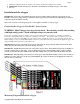
The eLogger’s LED
The eLogger’s LED indicates the device’s status.
Once the eLogger is powered up in your model, it will repeatedly flash a sequence of one, two or three flashes every second or so.
This flash rate is longer or shorter depending on the capture rate. This flashing indicates the following:
One Flash - The eLogger is actively recording. This is the normal power-up state.
Two Flashes – The eLogger’s buffer is full, or you have enabled logging triggers and the logger is not yet triggered. Note that the
eLogger will pause when the buffer is full only if you have selected the “stop on full” mode described above, when the memory is
filled to capacity with data.
Three Flashes – The eLogger is connected to your PC’s USB connector, and has been recognized by the PC.
After Your Recording Session
After operating your model with the eLogger, you can either remove the eLogger from your model and take it to your PC, bring the
model with the eLogger still in it to your PC, or (if you’re lucky) use a Laptop and connect to the eLogger in the field.
After you connect the eLogger to your PC’s USB interface, the LED should indicate USB connectivity with three repeating flashes as
described above.
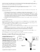
Once the eLogger is connected, launch the Application and click on the “Download” button. This will load the eLogger’s Data
Buffer into the Application for playback and saving.
Use the play controls to play back the data. Note that the Slider can be dragged with the mouse by clicking and holding it then
moving it to the desired position.
The application displays the following information:
• Notifications – this window displays messages about the recording. The three most common messages are: