
Owner's manual


Copyright © 2003-2007 Eagle Tree Systems, LLC
Page 4
After the sensor is glued and completely dry, remove the small spacer and rotate the drive train or propeller to ensure complete
freedom of movement. Also make sure that the sensor won’t vibrate and come in contact with the magnets during operation. If this
happens, the sensor will be destroyed, and the eLogger could be damaged.
Once these steps are complete, plug the Futaba style connector on the sensor into the eLogger as shown in figure 1. Note that a
standard Futaba style servo extension cable can be used to lengthen the RPM sensor wire if needed.
Using Existing RPM Sensors
Several of our customers have been able to use existing RPM sensors, such as governors or turbine sensors, with our products. The
following steps must be followed:
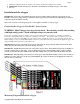
1) Determine the “pinout” of the existing sensor. Compatible sensors will have Power, Ground, and Signal connections. The
eLogger’s RPM pinout, from left to right, is: Power (black wire), Ground (red wire), Signal (white wire).
2) Devise a “Y” cable to connect your existing sensor to it’\s connection, and also to the eLogger’s RPM connection. NOTE:
Power for the sensor should come only from the connection the sensor is normally plugged into. So, only Gound and Signal
wires should be routed from the existing sensor to the eLogger. The power wire of the Y cable between the sensor and the
eLogger should be cut before connecting it to the eLogger. This is necessary to avoid connecting the power of the existing
sensor connection to the eLogger’s power connection.
3) Thoroughly test the system to make sure the sensor still works with whatever it was originally connected to, after Y’ing to the
eLogger.
Installing a Secondary RPM Sensor
A second MODIFIED Brushless RPM sensor can be plugged into the eLogger’s THROTTLE input, for measuring RPM of multiple
motors.
NOTE: the Optical and Hall Effects RPM sensors CANNOT be used as secondary sensors, and will be damaged if plugged into any
port other than the RPM port. Only the brushless RPM sensor can be used for secondary RPM.
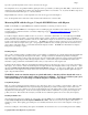
To measure secondary RPM, the RPM sensor must be modified as follows:
• Carefully pry back the plastic tabs that hold the RED and BLACK pins in the RPM sensor connector, and remove the red and
black pins.
• Replace the red pin where the black pin was, so that the pin order in the connector is RED, OPEN, WHITE.
• The second RPM sensor plugs into the throttle port with the red wire toward the label side of the logger.
• The black pin (left detached from the connector above) connects to the upper “Tmp 3” pin, nearest the label.
NOTE: The second RPM channel is automatically set up with the same sensor type and gear ratio as the primary RPM. So, it’s
important that the same type of sensor be used for primary and secondary RPM.
The secondary RPM sensor(s) are logged and displayed on the screens with the other parameters, as described below.
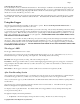
Monitoring your Model’s Throttle Position with the eLogger
Connecting the Throttle Servo Y-Cable to
your Throttle, and to the eLogger
IMPORTANT: Make sure you connect the
battery pack to the eLogger only AFTER
connecting the throttle Y cable to the eLogger
(and all other connections).
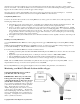
The eLogger logs
servo positions by measuring the pulses coming from
your receiver to the throttle servo, via the optional Y
cable. The Y Cable has 3 connections. The
“Futaba” male plug (at the “base of the Y”) connects
to the eLogger as shown in Figure. The universal
male and female plugs of the Y cable connect to your
receiver’s throttle channel, and to your throttle servo,
respectively. See Figure 2 for connections of the Y
cable to your Receiver and Servo.