
User Manual


Copyright © 2003-2010 Eagle Tree Systems, LLC
Page 11
function test your model once the eLogger is installed to ensure that there is no impact on your system. Make sure that
your “antenna down” operating range is within the manufacturer’s specifications. See your Radio owner’s manual for the correct
procedure for your equipment. DO NOT OPERATE IF YOUR MODEL DOESN’T PASS THE ANTENNA DOWN RANGE
CHECK.
Additionally, you need to make sure that your Model’s power system is working correctly after adding any new hardware in-line, like
the eLogger. This is especially critical in high amperage/voltage installations. It’s important that you safely run your model in an
extended stationary “bench” test, similar in duration and power usage to your most aggressive modeling, to ensure there are no
problems with any connections, etc. DO NOT OPERATE YOUR MODEL IF YOU HAVE PROBLEMS DURING THIS
EXTENDED STATIONARY TEST!
The eLogger’s LED
The eLogger’s LED indicates the device’s status. Note: sometimes the eLogger’s LED is hard to see from the top, but should be
visible from the side of the eLogger.
When the eLogger is powered up in your model, it will repeatedly flash a sequence of one, two or three flashes every second or so.
This flash rate is longer or shorter depending on the capture rate. This flashing indicates the following:
• One Flash Sequence - The eLogger is actively recording. This is the normal power-up state.
• Two Flash Sequence – The eLogger’s memory buffer is full, or you have enabled logging triggers and the logger is not yet
triggered.
• Three Flash Sequence – The eLogger is connected to your PC’s USB connector, and has been recognized by the PC.
After Your Recording Session
After operating your model with the eLogger, connect the eLogger to USB and download the data.
After you connect the eLogger to your PC’s USB interface, the LED should indicate USB connectivity with three repeating flashes as
described above.
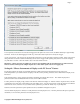
Once the eLogger is connected, launch the Software and click on the “Download” button in the “Recorder Data Operations” section
of the main screen. This will load the eLogger’s memory buffer into the Software for playback and saving.
Use the play controls to play back the data. Note that the Slider can be dragged with the mouse by clicking and holding it then
moving it to the desired position.
The software can display the following information:
• Notifications – this window displays messages about the recording. The three most common messages are:
o Startup/Reset Detected – this indicates that the eLogger has been turned on at the time specified
o eLogger low battery restart – this indicates that the eLogger has ‘rebooted’ because the power momentarily dropped
below around 4.5 volts. See the troubleshooting section if you frequently see this message.
• Length/Progress – when stopped, this readout indicates the total recording length. When playing back, this meter indicates
current time into the session.
• Graphical and/or Numeric Pack Voltage – The software displays the current or max (when playback is stopped) pack
voltage readings in either gauge or numeric format.
• Graphical and/or Numeric Pack Current – The software displays the current or max pack amperage readings in either
gauge or numeric format.
• Pack Wattage – this gauge indicates the pack wattage during playback.
• Cumulative Amp-Hours – this numeric display indicates the cumulative AH used
• Graphical and/or Numeric Temperatures – The software can display up to three Temperature readings in either gauge or
numeric format.
• Graphical and/or Numeric RPM – The software displays RPM readings in either gauge or numeric format.
• Graphical and/or Numeric Airspeed – The software displays airspeed readings in either gauge or numeric format.
• Graphical and/or Numeric Temperatures – The software displays temperature readings in either gauge or numeric format.