
User Manual

USER GUIDE
69
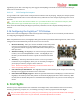
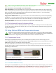
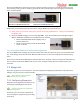
The simple modification of the sensor involves carefully removing the sensor’s red and black wires from the
servo housing, using a probe or needle to gently lift the tabs on the housing, and reversing the red and black
wires, as shown below.
Additionally, the following should be noted about using an RPM sensor with the Vector:
1) Never power your receiver with greater than 6V when using an RPM sensor. Doing so could damage
the RPM sensor.
2) Dropouts of RPM readings can occur with high RPMs. If you see the RPM sensor reading 0 at higher
RPM, an additional modification to the RPM sensor is required:
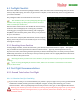
a. Obtain an MA2C029TAF diode at digikey.com, or
another distributor.
b. Install it in the black wire of the brushless RPM
sensor, as shown.
7.2.2.2 Brushless RPM Sensor Hookup and Configuration
For correct RPM sensor readings, you need to let the Vector know the number of “poles” your brushless motor
has. This setting is entered in the “Num Brushless Motor Poles” section of the Calibration and Sensor Setup
menu.
Please refer to the Brushless RPM Sensor manual found on the “manuals” tab of our website for information on
how to connect the brushless RPM sensor to your motor, and how to determine the number of poles your
motor has.
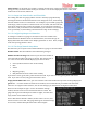
7.3 Waypoints
The Vector supports up to 26 waypoints. The Vector displays the Waypoints graphically on the OSD screen,
making it easy for you to fly to them manually.
At this time, the Vector will not
autonomously fly to waypoints.
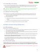
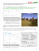
7.3.1 Configuring Waypoints
Waypoints are configured in the software, by
selecting the “GPS Waypoints Setup” tab.
Internet connection is required to
configure waypoints.
On this tab, you can zoom in to the desired
area, and add your waypoints by just clicking
on the map.
RPM Sensor BEFORE Modification RPM Sensor AFTER Modification