
User Manual

USER GUIDE
19
Note that the voltage supplied to the red wire of the “Camera/Mic” power input connector “D” on the
video harness will be supplied to the red wire on the “Microphn” audio harness connector.
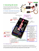
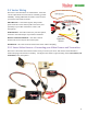
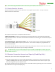
3.5.4 Vector Receiver Harness
The Receiver Harness is used to connect the Vector to the outputs of your receiver. The pin-out for the
Receiver Harness is shown below.
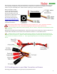
Three types of receiver inputs are supported with the Vector:
Traditional (parallel): each of the relevant harness connections needs to be connected to the appropriate
output port on the receiver. See section 3.5.7 below for information on connecting the receiver harness inputs
to your receiver.
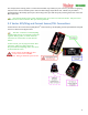
Serial PPM (SPPM) and S.BUS™ (serial modes): only the “Ail” connector of the receiver harness should be
connected to the SPPM or S.BUS™ output of your receiver. Your receiver’s outputs are programmed in the
Vector, as described later.
Note: Connect only the “Ail” wire to your receiver when using a serial mode. Never connect other wires from
the receiver harness to your receiver if you are using a serial mode!
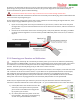
To reduce wiring, if you use a serial mode you can use a needle or small probe to carefully pry up the
tabs of the other connections of the receiver harness, remove the unused wires, and save them for later use. Or,
just trim off the extra wires.
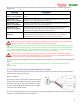
3.5.5 Receiver Connection Harness Load Capacity (Fixed Wing Only)
Do not power your receiver with a voltage higher than 16V.
With typical fixed wing electric model wiring, the ESC’s BEC is connected to the Vector’s throttle output
channel. This BEC powers the servos, and all servos are connected to the Vector’s servo outputs. If you
have this configuration, please skip this section.
Also, skip this section if you do not have large servos, or if the BEC or battery powering your servos is rated at 6
amps continuous or less (the vast majority are).