Vector Flight Controller + OSD User Guide June, 2014 Version 1.7 Software Version 11.34+ © 2014 Eagle Tree Systems, LLC. All Rights reserved.
USER GUIDE Table of Contents 1 Safety ............................................................................................................................................................................. 6 1.1 .... Read the Manual!................................................................................................................................................................6 1.2 .... Special Symbols used in the Manual ..................................................................
USER GUIDE 4.1.1 Mounting Location and Orientation ................................................................................................................................ 26 4.1.2 Mounting Technique............................................................................................................................................................... 26 4.2 .... Mounting the GPS/MAG Sensor ........................................................................................................
USER GUIDE 5.11.1 Setting Controller Gains ................................................................................................................................................. 42 5.11.2 Verifying Correct Control Surfaces Movement (Fixed Wing) ....................................................................... 45 5.11.3 Confirming ESC Endpoints are set Correctly (Multirotor only)................................................................... 46 5.11.
USER GUIDE 6.3.3 Optimal Fixed Wing leveling ............................................................................................................................................... 64 6.4 .... Return to Home Testing and Operation ................................................................................................................ 64 6.4.1 RTH Limitations........................................................................................................................................
USER GUIDE 1 Safety The Vector is intended to be used exclusively for recreational purposes in model planes, boats and cars. Using the Vector for other purposes is not supported. Further, using the Vector in situations where its use or failure could result in loss of life, bodily injury or property damage is expressly prohibited. Eagle Tree Systems, LLC, is not responsible for your use of this product, or for any damages or injuries you may cause or sustain as a result of its usage. 1.
USER GUIDE RC models and accessories are not toys! The Vector should not be used by children. The Vector is intended for recreational use only, in model model aircraft. Any other use is not supported, and any use You should always use a spotter if your eyes are not on your model. For USA customers, please refer to the Academy of Model Aeronautics Safety Code at http://www.modelaircraft.org/files/105.PDF and FPV related code at http://www.modelaircraft.org/files/550.
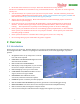
USER GUIDE 2.2 Packing List Your package should include the following: Vector Controller Current Sensor/PSU (DeansTM, XT60TM or wire leads version), GPS/Magnetometer (GPS/Mag), with GPS stand, clip and screw Video, Audio (not shown), GPS, and Receiver Harnesses 2.
USER GUIDE 2.4 How to Get Help and Request New Features Eagle Tree is committed to providing great customer service. Once you’ve read the manual, if something is not clear, just ask. We’d much prefer to take the time to answer your questions, rather than having you waste your valuable time struggling with an issue. To get help 24/7, visit the Eagle Tree Vector support thread on RCGroups: http://www.rcgroups.com/forums/showthread.php?t=2032857 Or, visit the thread on FPVLab: http://fpvlab.
USER GUIDE 2.5.3 Updating your Vector Firmware Even if you will be configuring the Vector using the stick menus, it’s a good idea to keep your Vector firmware updated, in case we add a feature or resolve an issue that is relevant to your airframe. Our latest software always has the latest Vector firmware included with it. To check to see if you have the latest firmware, first check what firmware version is installed on your Vector, which is displayed at the bottom of the Vector boot-up OSD screen.
USER GUIDE 2.7 Glossary of Terms used in the Manual Here are definitions for some of the terms used throughout the manual. FPV – FPV stands for First Person View. If you are not familiar with FPV, there are many websites devoted to it. Our FPV overview web page at http://www.eagletreesystems.com/OSD has a brief tutorial on FPV, which is a good place to start. OSD – OSD stands for On Screen Display. The OSD shows flight information, overlaid on the video camera image. RTH – Return to Home.
USER GUIDE Mode Switch – A two or three position switch on your radio transmitter which you have configured to control the “Mod” input on the Vector’s Receiver Connection Harness. Toggle – One fairly rapid movement the Mode Switch between its extents. (UP/DOWN or DOWN/UP) Configuration Gestures – A series of toggles of the Mode Switch. The number of times you toggle the switch determines which configuration step is performed. PSU - Power Supply Unit.
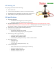
USER GUIDE 3 Connecting the Vector This section describes the Vector’s cabling and connections, and how to connect the Vector to your RC receiver, your servos or ESCs, and your FPV video transmitter and camera. 3.1 Vector Controller Connections The figure below shows the function of each of the Vector’s ports, and other Vector information. 3.1.
USER GUIDE For example, if the backup power is connected to the BEC of your ESC (via your receiver), and that is supplying 5.0V, the Vector will use the PSU power unless the PSU voltage drops below 4.5V. Likewise, if your BEC is providing 6.0V to the backup power port, the backup power port will always be powering the Vector unless the BEC output fails. Note that the backup power input will NOT power your camera or video transmitter.
USER GUIDE 3.3 Vector Current Sensor/PSU Power Output The Vector’s high efficiency and low noise PSU accepts up to 6S voltage input, and provides filtered 5V and up to 12V output at 1A max per channel. It's perfect for powering most FPV gear, and can also power your receiver on multirotors (when NO servos are being powered by the RX!), eliminating the need for an external BEC.
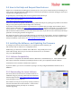
USER GUIDE 3.5 Vector Wiring The Vector’s wire harnesses are shown below. Note that a set of replacement wire harnesses is available (p/n VECCAB-SET). Having additional sets make it easier to move your Vector from model to model. Video Harness – routes video signals, and provides power from the Current Sensor/PSU to the Vector, and optionally to your video transmitter, camera, and microphone. Audio Harness – this cable connects to your microphone, and also to the audio output of your video transmitter.
USER GUIDE The first step to wiring your camera and transmitter is to install servo connectors on the wire harnesses that came with these components, if they don’t have them already. Servo connectors and crimpers are available online or at your local hobby store. Either Futaba™ or JR™ style connectors will work. Refer to the figure at right. Consult the manuals for your camera and video transmitter, identify the signal, power and ground wires, and install the servo connectors on these wires.
USER GUIDE Here are typical wiring strategies, depending on the number of batteries desired, transmitter and camera voltages, etc. Video Setup Wiring Method Single Battery, 12V camera, 12V transmitter Connect both red PSU power taps “A” to camera and transmitter power inputs “D” and “E” Single Battery, 5V camera, 12V transmitter Connect the white PSU power tap “B” to camera power input “D”. Connect a red PSU power tap “A” to transmitter power input “E”.
USER GUIDE Note that the voltage supplied to the red wire of the “Camera/Mic” power input connector “D” on the video harness will be supplied to the red wire on the “Microphn” audio harness connector. 3.5.4 Vector Receiver Harness The Receiver Harness is used to connect the Vector to the outputs of your receiver. The pin-out for the Receiver Harness is shown below.
USER GUIDE If, however, the AIL lead of the Vector’s receiver connection harness takes power from your receiver, and this powers large servos you have connected to the Vector, OR, you have large servos connected to both your receiver and the Vector, please read the following: You should not allow more than 6 amps continuous current to flow through the AIL wire.
USER GUIDE damaged if the red wires are connected together. c) Or, be sure to never connect your main pack to the current sensor without having the ESC main power connector also plugged into the current sensor. If one of these steps is not followed, your ESCs will receive power even when the ESC main power connector is not plugged into the current sensor.
USER GUIDE 3.5.7 Connecting Receiver and Servos/ESCs to the Vector First, connect your ESC or servo wires to the Vector output ports without powering the Vector, to make sure they reach the desired Vector mounting location. Then disconnect them before proceeding to the configuration section.
USER GUIDE The chart below shows typical receiver and servo/ESC connections for these airframe types. * The Receiver Output and Vector Rx Harness sections do not apply to SPPM or S.BUS™ receiver modes.
USER GUIDE Airframe Vector Airframe Type V-Tail with Ailerons (cont.
USER GUIDE 3.5.8 Connecting you Receiver’s RSSI Output (if available) Note: If you have a PPM capable receiver that outputs RSSI and/or link quality in the PPM stream, instead of through a separate wire, skip to the next section. If you wish to display the receiver’s signal strength (RSSI), and your receiver supports this feature, you will need to connect the top (signal) pin of the “RSSI/5V Backup” connection of the Vector to your receiver’s RSSI output.
USER GUIDE 4 Mounting the Vector and Accessories 4.1 Mounting the Vector 4.1.1 Mounting Location and Orientation Mount the Vector flat and level with the label facing toward the sky and the red arrow on the Vector case facing toward the nose of your model (the direction of forward travel). The Vector should be mounted as near to the model’s Center of Gravity (CG) as practical. Ideally, the Vector will be mounted with the mark shown in section 3.1 (just behind the red arrow) directly above your model’s CG.
USER GUIDE 4.2 Mounting the GPS/MAG Sensor 4.2.1 GPS Signal Interference RF noise from video transmitters, cameras, and other devices can interfere with GPS reception. It’s important to mount the GPS/MAG as far away from these sources as practical. Also, obstructions such as trees or buildings that block the Vector from having a clear, unobstructed view of the sky can cause issues with GPS reception.
USER GUIDE 4.2.4 The GPS Stand and Clip The GPS Stand is designed for multirotors, where it lifts the GPS/MAG sufficiently above the multirotor frame to avoid electromagnetic interference. However, it can be used for any type of model. The stand must be mounted vertically, and the base can be mounted either by placing it under 2 or more of the multirotor’s arm mounting bolts, or with closed cell, double sided foam tape. The stand also has a slot that can be used to neatly route the GPS cable.
USER GUIDE 2) The static holes on the pitot tube (shown in the figure) should extend at least 1/2” (13mm) past the wing’s leading edge or the nose cone, or past any other obstructions - the farther out, the better. This is to ensure that the static holes and pitot pickup are in undisturbed air. 3) For prop planes, it’s important that the tube be placed so that it is not directly in the plane’s prop-wash, which will result in erroneous readings.
USER GUIDE 4.5.4 The Kill Switch (for Multirotors Only) The kill switch is an optional control for multirotors that can be used to instantly kill all motors. This can be especially useful for initial flight testing. A momentary (spring loaded) switch can help reduce the likelihood of inadvertent triggering. The kill switch can be mapped to the “Aux” input of the receiver harness, or to an SPPM or S.BUS™ channel.
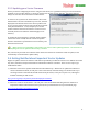
USER GUIDE 5.3 Configuring with the Windows Software The manual focuses primarily on configuring the Vector using the stick menus, but the concepts are the same for the software. Generally, the Vector can be more quickly and easily configured with the software, especially for first time users. However, both methods have been made as straightforward as possible. To configure with the Software, follow these high level steps.
USER GUIDE 9) With the Vector and the model perfectly level, record flat level mounting by clicking the “Record Flat Level” button. Now, the artificial horizon (AHI) display should show level, and should closely follow your movements as you pitch and roll the model. If the AHI is moving sluggishly and not keeping up with your movements, or is rotating on its own, DON’T FLY and contact support. 10) Configure sensors and the compass by clicking the “Configure Compass” button.
USER GUIDE IMPORTANT: follow these instructions carefully. If you make a mistake, it may be impossible to continue with stick menu configuration, since the Vector menus cannot be accessed unless the Vector knows the mappings for the Mode switch and the control stick.
USER GUIDE This should initiate menu mode, and the Main Menu should appear. To navigate menus, the elevator stick is used to scroll up and down the menu list. The aileron stick is used to select or deselect a menu item. When a menu item is selected, the elevator stick is used to increase or decrease the value of the parameter being changed.
USER GUIDE changed to their default values for that airframe type. making other settings. So, remember to change the airframe type first, before Make sure the airframe type is correctly selected! If a fixed wing airframe type is selected with a multirotor, the propellers can spin uncontrollably at high speed at power-up! Likewise, if a multirotor airframe type is selected with fixed wing, the servos can be pushed beyond their endpoints and be destroyed! 5.
USER GUIDE Next, invoke menu mode, select the “Run Receiver Analysis Wizard” menu item under the “New Airframe Checklist” menu, and follow the instructions below: Wizard Prompt DISCONNECT MOTOR/Toggle Mode What to Do Make sure your motor(s) or propeller(s) are disabled, and toggle the Mode switch up and down to continue. During the wizard, the Vector shuts off the Vector throttle output channel for fixed wing, and all the Vector output channels for multirotors.
USER GUIDE 5.9 Configuring Auxiliary Receiver Inputs and Servo Outputs The Vector lets you configure several different auxiliary inputs (for transmitter mixed second aileron and other secondary control surfaces) and for additional Vector control inputs. Also, for fixed wing models, the Vector lets you configure up to two auxiliary servo outputs, for secondary servos. 5.9.1 Configuring the Auxiliary Input Channel (for non-serial Rx inputs) For serial Rx modes (SPPM and S.
USER GUIDE 5.10 Flight Modes, and Configuring the Mode/Submode Switches 5.10.1 Flight Mode Description The Vector supports a wide variety of flight modes, which you can select in flight using your Mode switch, and optionally a Submode switch. The table below describes these modes, and also indicates whether the GPS (with a good 3D fix) and the magnetic compass are required. The fallback flight mode is listed for when either the GPS or Compass is deemed untrustworthy.
USER GUIDE heading. Not recommended for FPV flying. (see figure below) (Compass required) Cartesian with Loiter C+L Same as Cartesian, but holds horizontal position using GPS when control stick is centered.
USER GUIDE 5.10.2 Control Stick Function in Multirotor Modes The figure below shows the behavior of the multirotor when the control stick is moved, for the presently selected flight mode. 5.10.3 Programming the Mode Switch During flight, you can change the Vector flight mode using your mode switch, and optionally a submode switch for additional flight modes. The position of the mode switch determines the flight mode, and can also be programmed to turn off the OSD screen during flight.
USER GUIDE 3D+HdgHld Selects Direct Rate 3D Flight Mode (with Attitude Hold) Gyro Stab Selects ’gyro’ stabilization mode Stab Off Turns off the stabilizer Cartesian Selects Cartesian Flight Mode Cart Loit Selects Cartesian Flight Mode with Loiter (GPS) Polar Selects Polar Flight Mode (GPS) Polr Loit Selects Polar Flight Mode with Loiter (GPS) Center Stick Selects Center Stick Stabilization Flight Mode RTH Test Engages RTH test mode (GPS) Dsply Off Turns off OSD Display.
USER GUIDE Polr Loit Selects Polar Flight Mode with Loiter (GPS) Center Stick Selects Center Stick Stabilization Flight Mode RTH Test Engages RTH test mode. (GPS) 5.
USER GUIDE not high enough, the wings may not return to level quickly (or at all) when you release the sticks. If a gain value is too high, the Vector may push your control surfaces or motors too hard to return to level, which can cause oscillations.
USER GUIDE 5.11.1.3 Gain Adjustment for Initial Flight The default gains for the Vector were chosen so that most airframes will fly reasonably well without major adjustments. However, airframe types vary widely, so the default gains may cause problems with your model. There are three ways to reduce the likelihood of gain related problems with your first flights: a) Set up a gain knob as described below, so you can control the gains of one or more axes quickly from your radio, during flight.
USER GUIDE adjustable in the “Advanced Setup” menu. The basic gains act as a multiplier on top of the inner loop PID gains. For example, increasing the Pitch/Elevator Basic Gain has the effect of increasing each of the Inner P, I, and D pitch gains by the same proportion. Pitch and Roll: The “Maximum Pitch” and “Maximum Roll” angle settings control the maximum pitch and roll to which your model will be commanded by the controller, when in a 2D mode.
USER GUIDE Correct and Incorrect Control Surface Movement 5.11.3 Confirming ESC Endpoints are set Correctly (Multirotor only) For correct multirotor operation, all of your ESC endpoints must be set the same, so that the idle throttle setting causes each motor to spin at the same speed, and so that the full range of your throttle is utilized by the ESCs. Consult the manual for your ESCs to determine how to set endpoints, and set them all the same.
USER GUIDE The propellers will spin when the multirotor is armed. Do not arm your multirotor with propellers attached until you’ve verified that motor direction, propeller direction, motor order, idle throttle and other settings are correct! Make sure you don’t inadvertently move the stick(s) to the arm corner! The multirotor is disarmed by moving the throttle stick to the off position, and holding the rudder stick in the leftmost position for 1 second.
USER GUIDE flight. If set too high, the multirotor could take off or flip over when armed! Typically, a good idle throttle value will range from 1150 to 1200 microseconds. However, this can vary from ESC to ESC, and may depend on your ESC endpoint settings. Consult your ESC manufacturer for recommendations. One way to adjust idle throttle (without propellers installed!) is to set the value low, arm the multirotor, and observe the motors.
USER GUIDE you are in an altitude hold enabled flight mode, your throttle setting will be reduced, requiring about 90% throttle to climb. If you are in a non-altitude hold flight mode, the low battery alert will appear, but the throttle will not be affected. To configure this feature, invoke menu mode and bring up the “Multirotor Configuration” menu from the main menu. Here you can turn autoland on and off, as well as setting the cell voltage for landing.
USER GUIDE 5.12.1 Configuring Failsafe Detection You MUST have a receiver that lets you program failsafe positions to use RTH. All modern receivers should support this. The Vector can detect failsafe in one of 3 ways, depending on your receiver’s capabilities. First decide which method you want to use below, and then tell the Vector which method to use by invoking menu mode, navigating to the “Safety Configuration Menu”, and changing the “Failsafe Detection Method” item as described below.
USER GUIDE 5.12.2 Configuring RTH/Safety Mode 5.12.2.1 Selecting the Desired Safety Mode The Vector has a few options for what to do when failsafe is detected, referred to as “Safety Modes.” To select the desired failsafe option, invoke the “Safety Configuration Menu” and change the “Select the Desired Safety Mode” item.
USER GUIDE This is not recommended for line of sight flying, since the multirotor will likely be pointing in a different direction than when you last had control over it, which can be confusing for line of sight. Advanced Return to Home Options: There are several advanced options that can be configured for RTH, under the “Advanced Setup…” menu. These are described in the Advanced Features section in the document. 5.12.
USER GUIDE Multirotor is armed, but an error has been detected. Check the OSD notification area to determine the cause of the error. Multirotor is armed. A 2D Flight Mode is selected A 3D flight mode (including ‘gyro mode’) is selected A Loiter flight mode is selected USB mode is active 5.14 Configuring the OSD The Vector’s built-in color OSD has many advanced features and display options. Even so, it can be easily configured to display basic information that is sufficient for most pilots.
USER GUIDE If the OSD information is too wide for your screen, select Narrow Screen Mode. If you have trouble reading the text, try changing the black level, or changing the colors of the text, as described below. To change color settings, select the “Color Setup” menu. You can change the color brightness, intensity, and hue in this menu. Also, you can select which colors to use for text and graphics.
USER GUIDE 5.14.4.2 Altitude, Speed and Distance Readouts Barometric Altitude: This displays the present barometric altitude of the model from the built in pressure sensor, which is zero referenced (set to zero) when the Vector is powered up. GPS Altitude: This displays the present GPS provided altitude, assuming there is a 3D GPS fix. This is also set to zero at power up.
USER GUIDE Never: GPS position is never displayed Trouble: GPS position is displayed when radio failsafe is detected, if RTH is triggered, or if an alarm has been triggered. Low Alt: GPS position is displayed for Trouble, and additionally will display if the present altitude is less than 100 feet/30meters. Distance: GPS position is displayed for Trouble, Low Alt, and additionally if the distance of the model from home exceeds the “RADAR Maximum Radius” menu item in the “Graphics and Indicators Setup” menu.
USER GUIDE The circular indicator in the center of the screen (Home/Center Screen marker) marks the home point, in a "bird's eye" view map. The RADAR location and direction of travel indicator (the chevron) indicates where the model is in relation to home. As your model moves relative to home, the chevron moves relative to the center of the screen. Also, the direction the chevron is pointing indicates the direction the model is traveling, relative to home.
USER GUIDE 5.14.6.6 Motor Battery Gauge The motor battery gauge graphically shows the main pack’s remaining mAH. Note that the total mAH must be set correctly for this feature to be accurate. 5.14.6.7 Home/Center Screen Marker Places a small circle with “T” in the center of the screen. 5.14.6.8 Flight Mode Indicator This indicator displays a 2 or 3 digit code for the flight mode presently being used. See the “Flight Mode Indicator” column in the table in section 5.9.
USER GUIDE To be able to see when an alarm has triggered, you must have the numeric readout for it displayed, so that you can see it flash. 5.14.7.1 Low Pack Voltage Alarm The alarm for pack voltage is set by specifying the per cell voltage that will trigger the alarm. The Vector automatically detects the cell count for your pack, so you can switch between packs of different cell counts, without needing to reset the alarm each time. 5.14.7.
USER GUIDE 5.15.2 Calibrating the Compass Compass calibration should be done with the model away from electrical fields and metal objects. The best place to calibrate the compass is outdoors, at the field where you will be flying. 5.15.2.1 Steps before Calibrating Before calibrating the compass, make sure that the compass is installed correctly, and that all equipment you plan to fly with, including cameras, canopies, etc., are fully installed on the model, and turned on.
USER GUIDE significantly (more than a few degrees), that suggests the GPS/Mag is mounted too close to electrical wiring or other sources of interference. 5.15.3.2 Field Testing the Compass It’s a good idea to do a quick check of compass function before each day of flying. Display the compass (either on the Preflight Checklist menu or the main OSD screen) and make sure the compass is pointing in the correct direction.
USER GUIDE 6.1 Preflight Checklist The Vector includes an interactive preflight checklist, which lists some of the common things that you should check (or do) before flying. Of course, no generic list is complete, so this should only serve as a supplement to your normal checklist. The preflight checklist is invoked from the main menu. The cumulative time you will spend going through your checklist before flying is probably much less than the time it takes to rebuild your model once.
USER GUIDE 6.2.1.2 Control Direction check for Multirotors If you can do so safely, after arming the multirotor and verifying that the motors are turning in the correct directions, do the following: If you’re in an altitude hold mode, activate the stabilizer by quickly moving the throttle past the halfway point and quickly back down. If you’re in a non-altitude hold mode, activate the stabilizer by moving the throttle up slightly, and quickly back down.
USER GUIDE 6.3.2 Fixed Wing in-air leveling If your model is not flying straight and level in 2D Mode WITHOUT Hold, first level out the model with your control stick, then (while keeping the model level with the stick) toggle the mode switch 5 times. This records the level flight orientation for your model. The Vector remembers your control stick position the moment you first start to move the mode switch.
USER GUIDE 6.4.3 In-air RTH Testing The simplest way to test RTH in the air is to program a mode/submode switch position to “RTH Test”. When this switch position is selected, RTH should engage, and your model should fly toward the home point. Never intentionally turn off your radio to test RTH in the air.
USER GUIDE Display parameter as: This item lets you select the display mode of the readout, as Text, Gauge, Swatch, or Swatch with Text. See the Gauge and Swatch section below. Show on Scrns: This item lets you select which screens (1 through 6, or a combination thereof) on which this readout will display. Display on which Row: The Vector’s numeric readout display consists of 5 columns (from left to right) and 4 rows (from top to bottom), letting you display a total of 20 numeric readouts on each screen.
USER GUIDE Swatch format – In this mode, the readout is a simple colored square, with programmable color changes, letting you easily see when readout needs your attention. You can also display the numeric value of the readout next to the swatch, if desired. 7.1.2.1 Gauge and Swatch Colors and Thresholds The reading and color of a gauge (and the color of a swatch) is programmed by selecting the numeric thresholds for which a color change will occur, and selecting the total number of colors to choose from.
USER GUIDE Until you enter the WORST value below, and autofill the thresholds, a warning about the thresholds being incorrect will appear at the bottom of the menu. This is normal. Color Threshold 1, Color Threshold 2, Color Threshold 3, Color Threshold 4: The color thresholds let you set the values for the readouts where the color changes will occur. The simplest way to set these up is to set up the best and worst values, and select “Autofill Thresholds” below.
USER GUIDE The simple modification of the sensor involves carefully removing the sensor’s red and black wires from the servo housing, using a probe or needle to gently lift the tabs on the housing, and reversing the red and black wires, as shown below. RPM Sensor BEFORE Modification RPM Sensor AFTER Modification Additionally, the following should be noted about using an RPM sensor with the Vector: 1) Never power your receiver with greater than 6V when using an RPM sensor.
USER GUIDE You can also configure the first waypoint (Waypoint A) to be the home position. This lets you set the home point without needing to move the model physically to that point. Check the “User Waypoint A as Home Position” checkbox to enable this feature. For the Home Waypoint feature to work, the model must get its first GPS position fix within about 500 feet (152 meters) of the programmed home waypoint.
USER GUIDE Several additional options are available for choosing when to log data, which data to log, and how often to log data. These options can be configured under the “Data Logging Setup” menu. If you choose to have data logging stop when the buffer is full, don’t forget to clear the logging buffer before each flight, from the Preflight menu. 7.4.
USER GUIDE 7.4.2.5 Saving and Loading Data Files To save a data log file for later use, click the “Save Logged Data To Disk” button in the “EagleEyes and Data Logging” tab of the software. To load a previously saved file, click the “Load Data File from Disk” button. 7.4.2.6 Using Excel™ to View Data The log files are compatible with Excel ™ spreadsheet software, and other spreadsheet products supporting space delimited data files.
USER GUIDE follows: Disable: The second (inner) RTH altitude settings are ignored. This is the default. Normal: When your model comes closer than the “Home Altitude Radius” set below, and RTH is active, the model will descend or climb to the "Home RTH Altitude" specified below, and return home per your settings.
USER GUIDE The variometer produces a varying tone, which changes as you ascend or descend at different rates. When ascending, the tone will be broken into pulses, with the tone frequency and the frequency of the pulses increasing as the rate of ascent increases. When descending, the tone will be continuous, with the tone frequency decreasing as your rate of descent increases.
USER GUIDE 7.7.1 Electrical Calibration The voltage and amperage (current) readings for your motor pack, and the voltage readings for your transmitter pack, camera pack and receiver pack (if used) can be calibrated. These calibrations are performed in the “Electrical Calibration” menu.
USER GUIDE 7.8 GPS Configuration Several settings for the GPS are provided, on the GPS Configuration menu. 7.8.1 Choosing the GPS Position Display Format The GPS position can be displayed in 3 formats, controlled by the “GPS-On-screen display format” setting: Decimal degrees (DDD.DDDDD°) Degrees, minutes (DDD° MM.MMMM') Degrees, minutes, seconds (DDD° MM' SS.
USER GUIDE 8 Troubleshooting Issue My multirotor does not hold horizontal position well in the Loiter flight modes Solutions If you are using a high power video transmitter (especially 1.3GHz), try hovering with your video transmitter turned off to see if the issue goes away. If the transmitter is the cause, see the GPS Fix troubleshooting section below. Make sure your GPS module is getting an unobstructed view of the sky. Make sure your compass is calibrated correctly.
USER GUIDE Increase or decrease the “RTH/Loiter Circle Radius” setting in the Advanced RTH menu. RTH/Loiter: my fixed wing model circles too widely or too tightly around the loiter or home point See also the steps for troubleshooting if the model turns too fast or too slowly, above. Always keep the GPS/MAG as far away from your video transmitter antenna, and your video camera, as feasible. If you are using a 1.
USER GUIDE Make sure you are running the latest Vector firmware, as described in the “Firmware Update” section. Consider performing a “Factory Reset” on your Vector, which will restore the Vector to factory defaults. This can be done either with the “Factory Reset” button in the software (at the bottom of the screen) or with the option in the Advanced Radio Control stick menu.
USER GUIDE 9 Notification Messages During boot-up and normal operation, the Vector constantly checks its status and settings, and the status of any connected accessories. If an issue is detected, the Vector will display a message in the OSD notification area either temporarily or until the issue is resolved, depending on the importance of the message. The table below describes these messages, and what they mean. Note that it is unlikely you will ever see most of these messages.
USER GUIDE This message is displayed if an error has occurred with the optional altimeter calibration step. If you try to arm when the Vector is in RTH mode (normally because the mode/submode switches are set to “RTH Test”), this message will Can't arm when RTH triggered! appear. Calibration error- see manual Can't change when knob used! The controller gains cannot be changed in the menus when the gain knob is enabled for that gain.
USER GUIDE External bus error! Flight Battery Not Detected Flip crash detected! Disarmed Flyaway detected-Disarming! Freefall detected!!! Gain Knob used but undetected GPS Status: Awaiting first fix GPS Status: Awaiting 3D fix GPS Status: Awaiting Enough Sats GPS Status: Awaiting HDOP Accuracy GPS Status: Post-Fix Countdown GPS Not Connected! GPS Fix Lost! GPS/Compass has old Firmware! Gyro not detected! Home Waypoint too far away! Idle throttle being reduced! Impact Detected! Kill Switch Activated!! Lan
USER GUIDE Loiter Off - Poor GPS or Mag Low Battery Voltage Detected! Magnetometer not detected! Maximum Altitude Exceeded! Maximum Distance Exceeded! Memory malfunction detected! Menus disabled during flight! Mode Switch not detected Motor Kill Input not Detected Moving or gyro decalibrated! Multirotor is ARMED! Multi not level enough to arm Multirotor is DISARMED! Multirotor Stability Issue! Must enable gain knob first! Need non-GPS on Mode/Submode New Receiver Mode detected! No RTH! Mode Sw unprogrammed
USER GUIDE Outputs Off:bad Configuration Please arm in non-GPS mode! Please run RC Wizard! Power Brownout Detected! RTH Flyaway detectedLanding! RTH Engaged: Move sticks to cancel RTH Engaged: Too Many Rx Glitches RTH Engaged: Bad Rx Pulsewidths RTH Engaged: Rx Failsafe Detected Rudder Issue: Rerun Wizard! S-BUS Error Detected! Submode Input not Detected! Throttle Failsafe Incorrect! Throttle Issue: Rerun Wizard! Too much movement - aborting! USB Mode - Outputs Disabled Warning: Too much vibration The V
USER GUIDE 10 Description of Numeric Readouts The following numeric readouts can be configured for display. Some require optional hardware.
USER GUIDE 2nd Rudder Rx In % The measured pulsewidth at the Vector’s 2nd Rudder input, if used Aileron/M2 Output % The pulsewidth being sent to the Vector’s Aileron/M2 output (0% = 1 millisecond, 100% = 2 milliseconds) Elevator/M3 Output % The pulsewidth being sent to the Vector’s Elevator/M3 output Throttle/M4 Output % The pulsewidth being sent to the Vector’s Throttle/M4 output Rudder/M1 Output % The pulsewidth being sent to the Vector’s Rudder/M1 output Aux1/M5 Output % The pulsewidth being s
USER GUIDE Spektrum Ant L Fades “” Spektrum Ant R Fades “” Distance to Pilot The present horizontal distance between the home point and the model Line of Sight Distnc The present horizontal and vertical distance between the home point and model, calculated using the Pythagorean theorem Cumulative Distance The total distance traveled by the model since boot-up, in either miles or kilometers Home Arrow Indicates the direction the model is traveling, relative to the home point.
USER GUIDE 12 Limited Warranty Eagle Tree Systems, LLC, (ET) warrants to the original purchaser (the Purchaser) that the purchased product (the Product) will be free from defects in materials and workmanship for a period of one (1) year from the date of original purchase. This limited warranty is nontransferable.