
User Manual

Copyright © 2006 Eagle Tree Systems, LLC
http://www.eagletreesystems.com
Page
3
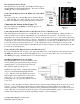
The surface to which the sensor is pointing should have alternating light and dark areas. The dark area must
NOT be shiny or reflective. It should be flat. For best results, half (180 degrees) of the surface should be
light, and half should be dark. If you are mounting the sensor near a spinning hub that is constructed light
colored material , a black magic marker (if the result is not shiny), flat black paint, or flat black electrical tape
can be used to color half of the circumference black. Or, if you are mounting it next to dark colored spinning
object (such as black plastic), you can use white paint, white tape, or a white paint pen to make half of the
circumference white. Note that if you are mounting on a black plastic spinning object, make sure that the
plastic is flat. It may be necessary to lightly sand it to take off any glossy surface. See Figure 3.
Note also that it is good to avoid direct sunlight onto the optical sensor, which can adversely affect readings. If
possible, shield the sensor from any direct sunlight.
Configuring the RPM Sensor with the Application
If you have not already done so, install your Data Recorder or eLogger in your model and set up the Recorder
software as described in your instruction manual.
In the Data Recorder Windows application, under “Hardware, Calibrate Motor RPM” choose “I am using the
Optical RPM Sensor.” Then, enter the number of light-colored stripes you have placed on the spinning surface,
and enter the Gear Ratio of your motor (normally 1.0) and choose the location that you have mounted the
optical sensor.
Troubleshooting
Below is a list of problems that may be encountered, and steps to remedy them. If your particular issue is not
addressed by the below, see the Support page on http://eagletreesystems.com or email
info@eagletreesystems.com. Include a full description of your problem, your machine configuration,
brands/models of receivers, transmitters and servos, application and Recorder firmware version if possible
(from Help->About in the app) and any other relevant details.
Issue: RPM is not working correctly
Solutions:
• Make sure your Recorder or eLogger has version 4.33 or greater firmware. Update to the latest
firmware from our website. See the “Supported Products” section above for more information on
updates – if your Recorder has 3.XX or 2.XX firmware, it must be upgraded by Eagle Tree on a fee
basis.
• Make sure that the parameters in the "Calibration->Calibrate Motor RPM" or “Calibrate, Calibrate
Ground Speed from RPM” are not set to zero. If this is zero, RPM will read zero.
• Make sure you have the sensor’s face the correct distance from the spinning object, and that the spinning
object is colored half light and half dark. Make sure that the dark portion is NOT glossy.
• For recording RPM, make sure that under Choose What to Log in the app, you have checked RPM.
• Make sure that the RPM sensor is plugged into the correct slot on the recorder or eLogger. Connect the
recorder to the computer and launch the app. Then, choose Tools->Live Mode. Make sure that the
RPM gauge is displayed, and spin the marked hub/axle, or wave the sensor in front of alternating light
and dark areas. See if the RPM reading jumps. If it does not, email support@eagletreesystems.com.
Limited Warranty
Eagle Tree Systems, LLC, warrants the Optical RPM Sensor to be free from defects in materials and workmanship for a
period of one (1) year from the date of original purchase. This warranty is nontransferable. If your unit requires
warranty service during this period, we will replace or repair it at our option. Shipping cost to us is your responsibility.
To obtain warranty service, email support@eagletreesystems.com for further instructions.
This limited warranty does not cover: