
User Manual

Copyright © 2006 Eagle Tree Systems, LLC
http://www.eagletreesystems.com
Page
2
How the Optical Sensor Works
The Optical Sensor works with your Data Recorder/eLogger to
measure RPM via reflected infrared light. The sensor contains
an IR light source, and an IR detector.
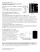
Connecting the Optical Sensor the Flight, Car or Boat Data
Recorder
The sensor plugs into your Data Recorder as shown in Figure
1. Make sure that you connect it in the correct location on the
recorder, and with the correct polarity (the plug is polarized).
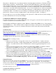
Connecting the Sensor to the eLogger V3
The Sensor plugs into the RPM port of the eLogger V3, as
shown in Figure 2A.
Connecting the 4 Wire Optical Sensor to the MicroPower V1 or MicroPower V2
The 4 Wire Optical sensor plugs into your MicroPower V1 or V2 as shown in Figure 2. Make sure that you
connect it in the correct location on the MicroPower, and with the correct polarity! Note that if you use a
temperature sensor along with the Optical sensor, the pin on the optical sensor’s loose wire can be snapped into
the spare slot in the temperature sensor’s connector. Alternatively, you can spin the temperature sensor around
so that the two wires are reversed, and the spare slot is hanging out over the edge of the MicroPower (it is ok to
reverse the polarity of the temperature sensor). If the temperature sensor is not being used, the pin on the
loose wire connects by itself to the pin on the MicroPower as shown, and the loose piece of heat-shrink should
be slid down to insulate the pin.
Connecting the 3 Wire Optical Sensor to the MicroPower V2
If you have the MicroPower V2 (large “V2” appears in white letters on the underside of the circuit board, near
the RPM pins) then you can use the 3 Wire Optical sensor. If you use the 3 Wire sensor, just connect the 3
Wire RPM sensor plug to the MicroPower V2, as shown in figure 2.
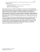
Installing the RPM Sensor in your Model
The Optical RPM sensor should be installed so that
its face (the flat part opposite the wiring) is facing a
spinning surface on your model, such as the prop
hub, flywheel, spinner, axle, gear, etc.
NOTE: best results will be obtained if the spinning
object is solid, with alternating light and dark
colors. This is because the Optical sensor has a
built in light source, which needs a solid object to
reflect off of. So, we do not recommend just
pointing the sensor at a propeller, which of course
is not solid.
The sensor’s face should be mounted so that it is about 1-4 mm from the spinning object. In most cases, closer
is better. It is not a bad idea to test the sensor at various distances using Live Mode (see your Recorder
instruction manual) to determine the best distance before permanently mounting the sensor, if this can be done
safely. The sensor can normally be glued into place, or mounted with heatshrink or tape to a self-constructed
bracket (brass tubing usually works well), depending on where you are mounting it.