
User Manual

Copyright © 2008 Eagle Tree Systems, LLC
http://www.eagletreesystems.com
Instruction Manual for the Airspeed MicroSensor V3
Document Version 1.5
Thank you for your purchase! This instruction manual will guide you through the installation and operation of your Airspeed MicroSensor
V3 (the MicroSensor). Please read the entire manual carefully before proceeding. If, after you read the manual, you have further
questions or problems, see the Support page on http://www.eagletreesystems.com for additional information, or email us at
support@eagletreesystems.com. Please visit our support web page for the full color, electronic version of this manual which may be
updated if changes were made after printing, or if you want to view the manual on your computer.
What the MicroSensor Does
The MicroSensor is a precision instrument that uses a Prandtl style pitot-static tube to measure airspeed, just as full sized planes do.
Advanced temperature compensation and calibration ensure the best possible accuracy. When used standalone, the MicroSensor displays
your maximum speed on the built-in 7 segment LED display. The maximum speed continues to be updated and displayed on the LED, until
you turn power off and on the MicroSensor. When power is turned off and on, the maximum speed from the last flight is displayed, and now
the MicroSensor is ready to record your next maximum speed (even if it is lower than the previous maximum speed).
Additionally, the MicroSensor can be connected to your eLogger (any version) to provide airspeed data for your entire flight. When
connected to the eLogger, airspeed can be displayed and graphed using the eLogger’s Windows software.
IMPORTANT: It is extremely unlikely that the installation of the MicroSensor will affect your model’s radio range or control. But, as
always after making an electronics change to your model, it is very important that you range and function test your model once the
MicroSensor is installed to ensure that there is no impact on your system.
Packing List
Your package should include the following: The MicroSensor, a machined brass and aluminum Prandtl style pitot-static tube, the Standalone
Cable, approximately 3 feet (1 meter) of small diameter silicon hose, and a printed version of this manual. NOTE: Additional Pitot Tube
kits are available for purchase on our website, for use with multiple models.
Installing the Pitot Tube and MicroSensor in your Model
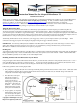
Using two lengths of the included small diameter silicon tube, the pressure and static connections of the pitot tube connect to the “+” and “-”
ports of the MicroSensor, respectively, as shown in Figure 1. It is best to mount the pitot tube in your model first, then determine where
you will mount the MicroSensor, and then cut the two lengths of silicon tube so they reach between the two.
Follow these guidelines when mounting the pitot tube:
1. The pickup end of the pitot tube (the silver colored tip) should be pointing toward the direction of the model’s travel. While best results
will be obtained if the pitot tube is perfectly aligned with the direction of travel in both axes, the “Prandtl” design of the tube will
compensate somewhat for higher angles of attack.
2. The static holes on the pitot
tube (shown on Figure 1)
should extend at least 1/2”
(13mm) past the wing’s
leading edge, or past any other
obstructions - the farther out,
the better. This is to ensure
that the static holes and pitot
pickup are in undisturbed air.
3. For prop planes, it’s important
that the tube be placed so that
it is not directly in the plane’s
prop-wash, which will result in