PCI30FG Series PCI PnP Analog Input Board User’s Manual PCI30G, PCI30GA, PCI30G32, PCI30GA32 PCI30F, PCI30FA, PCI30F32, PCI30FA32 Eagle Technology – Cape Town, South Africa Copyright © 1999-2002 www.eagledaq.
PCI30FG User Manual Analog Input Boards Data Acquisition and Process Control © Eagle Technology 31-35 Hout Street • Cape Town • South Africa Phone +27 21 423 4943 • Fax +27 21 424 4637 Email eagle@eagle.co.
PCI30FG User Manual Copyright All rights reserved. No part of this publication may be reproduced, stored in a retrieval system, or transmitted, in any form or any means, electronic, mechanical, by photographing, recording, or otherwise without prior written permission. Copyright © Eagle Technology, South Africa August 2002 Revision 1.
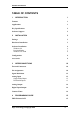
PCI30FG User Manual TABLE OF CONTENTS 1 INTRODUCTION 1 Features 1 Applications 1 Key Specifications 2 Software Support 2 2 3 INSTALLATION Package 3 Hardware Installation 3 Software Installation Windows 98 Post installation Windows NT/2000 4 4 7 8 Configuration 9 Accessories 9 3 INTERCONNECTIONS 10 External Connectors 10 Pin Assignments 10 Signal Definitions 12 Analog Input Single Ended Inputs Differential Inputs 12 12 13 Analog Output 14 Digital Input/Output 14 Counte
PCI30FG User Manual Digital Inputs/Outputs Reading the Digital Inputs Writing to the Digital Outputs 16 16 16 Counters Writing the initial counter value Reading a counter Configuring a counter 17 17 17 18 Analog Output Writing to a DAC channel 19 19 Analog Input Reading a single voltage from a channel Configuring the ADC subsystem for scanning Starting and Stopping the ADC process Getting data from the driver buffer Querying the ADC subsystem 20 20 20 22 23 23 5 25 CALIBRATION Requirements 25
PCI30FG User Manual Table of Figures Figure 2-1 Add New Hardware Wizard Step1 ..................................................4 Figure 2-2 Add New Hardware Wizard Step2 ..................................................5 Figure 2-3 Add New Hardware Wizard Step3 ..................................................5 Figure 2-4 Add New Hardware Wizard Step4 ..................................................6 Figure 2-5 Add New Hardware Wizard Step5 ..................................................
PCI30FG User Manual Table of Tables Table 3-1 External Analog Connector - SCSI-II-50F CENT............................11 Table 3-2 Internal DIO/CT Connector – IDC-40M ..........................................11 Table 3-3 External DIO/CT Connector - DB-37M ...........................................11 Table 3-4 Signal definitions ............................................................................12 Table 4-1 Counter Assignment.......................................................................
PCI30FG User Manual 1 Introduction The PCI30FG series are 32-bit bit PCI bus architecture data acquisition boards. They are available in two basic models, the G and F series. They can samples at 100kHz or 330kHz respectively. Addition to analog input, they also have analog output, digital input/output and counter-timer capabilities. For this reason the PCI30FG is an excellent all purpose data acquisition device with extensive analog input capabilities.
PCI30FG User Manual Key Specifications • • • • • • • • • A/D resolution: 12-bits D/A resolution: 12-bits DIO width: 8-bits CT width: 16-bits A/D non-linearity: less than ±0.75LSB A/D ranges: ±5V, ±10V, 0-10V A/D scan rate: 100kHz or 330kHz A/D, D/A interfaces via a 50 way SCSI right angle female centronics connector Digital I/O, Counter-timer via IDC40 Header Software Support The PCI30FG is supported by EDR Enhanced and comes with an extensive range of examples.
PCI30FG User Manual 2 Installation This chapter describes how to install and configure the PCI30FG for the first time. Minimal configuration is necessary; almost all settings are done through software. The PCI BIOS will assign an I/O base address and interrupt level. Package PCI30FG package will contain the following: • PCI30FG PCI board • EDR Enhanced Software Development Kit CD-Rom Hardware Installation This section will describe how to install your PCI30FG into your computer.
PCI30FG User Manual Software Installation Windows 98 Installing the Windows 98 device driver is a very straightforward task. Because it is plug and play Windows will detect the PCI30FG as soon as it is installed. No setup is necessary. You simply only have to supply Windows with a device driver.
PCI30FG User Manual Figure 2-2 Add New Hardware Wizard Step2 Select default option, search for best driver and select next Figure 2-3 Add New Hardware Wizard Step3 Select specify a location and enter the directory location of the driver on your EDR Enhanced SDK CD Rom \EDRE\DRIVERS\WDM\PCI30FG Select Next to proceed Eagle Technology © Copyright 2002 5
PCI30FG User Manual Figure 2-4 Add New Hardware Wizard Step4 Windows should have detected the proper driver and ready to install it. Select Next to proceed. Figure 2-5 Add New Hardware Wizard Step5 Click on the finish button to complete the installation. Click Yes to restart your computer.
PCI30FG User Manual Figure 2-6 Restart Your Computer Post installation After your installation was complete there is a few steps that can be followed to check that your installation was successful. • • First make sure that the driver is working properly by opening the system folder in the control panel. Check under the system device list if your board is listed and working properly. See picture below. Figure 2-7 System Properties • Clearly you can see that the PCI36C is listed and working properly.
PCI30FG User Manual • Further open the control panel and then the EagleDAQ folder. This dialog should list all installed hardware. Verify your board’s properties on this dialog. See picture below Figure 2-8 EagleDAQ Now the first part of your installation has been completed and ready to install the EDR Enhanced Software Development Kit. • Run setup.
PCI30FG User Manual Configuration Only the PCI30Gx series allows one manual setting. The PCI30Gx series has one jumper, LK1, to change the voltage span. The figure below shows the two different jumper settings. Figure 2-9 A/D Span Jumper Accessories The PCI30FG does have a wide variety of accessories that it can be connected too. See chapter on accessories.
PCI30FG User Manual 3 Interconnections The PCI30FG is designed so that there is a connector for analog signals and digital signals. The analog connector is on the bracket attached to the board and the other a connector on the PCB internal to the PC. External Connectors The PCI30FG does have two connectors, a SCSI-II-50 female centronics and an IDC40 male. The ICD40M can also be extended to the computer casing by making use of an extender cable and bracket that is supplied with the PCI30FG package.
PCI30FG User Manual 17 18 19 20 21 22 23 24 25 CHAN14 CHAN16 CHAN18 CHAN20 CHAN22 CHAN24 CHAN26 CHAN28 CHAN30 42 43 44 45 46 47 48 49 50 CHAN15 CHAN17 CHAN19 CHAN21 CHAN23 CHAN25 CHAN27 CHAN29 CHAN31 Table 3-1 External Analog Connector - SCSI-II-50F CENT Pin 1 3 5 7 9 11 13 15 17 19 21 23 25 27 29 31 33 35 37 39 Name PA0 PA2 PA4 PA6 PB0 PB2 PB4 PB6 PC0 PC2 PC4 PC6 DGND CNT0 COUT0 CGTE1 CNT2 COUT2 +5V DGND Pin 2 4 6 8 10 12 14 16 18 20 22 24 26 28 30 32 34 36 38 40 Name PA1 PA3 PA5 PA7 PB1 PB3 PB5 PB
PCI30FG User Manual Signal Definitions This sections deal with all the signals abbreviations.
PCI30FG User Manual CH0 V0 V15 CH15 AGND Figure 3-1 Single ended analog input Differential Inputs In differential input mode two multiplexer switches per channel are used. The A/D converter measures the difference in potential between the two channels. Channels are paired to form a single differential input. Channel 0 and channel 8 is used as channel 0, channels 1 and 9 etc. To connect see diagram below. It is also very important to know that each return connection must be referenced to analog ground.
PCI30FG User Manual In differential mode, all signal inputs to the PCI30FG must be referred to ground. This can be done by connecting a 1 to 10 kΣ Σ resistor from the low end of each input to ground. Analog Output The analog outputs come with sense lines and it is important to make sure that they are connected to the correct channel. If left unconnected the output will simple float at +10V or –10V. The analog output range is ±10V and is fully software configurable.
PCI30FG User Manual 4 Programming Guide The PCI30FG is supplied with a complete software development kit. EDR Enhanced (EDRE SDK) comes with drivers for many operating systems and a common application program interface (API). The API also serves as a hardware abstraction layer (HAL) between the control application and the hardware. The EDRE API make it possible to write one application that can be used on all hardware with common sub-systems.
PCI30FG User Manual Digital Inputs/Outputs The PCI30FG has 24 digital I/O lines, configured as 3 x 8-bit ports. The EDRE API supports auto direction configuration. By writing to or reading from a port, it is automatically configured as an output or input. A port is defined as a collection of simultaneous configurable entities. Thus in the case of the PCI30FG each port is only 8-bits wide. Reading the Digital Inputs A single call is necessary to read a digital I/O port.
PCI30FG User Manual Counters The counter sub-system is supported by functions to Write, Read and Configure. There are 4 counters that are available to the user and are compatible with the industry standard 8254 counter-timer. The table below shows all counters and their assigned function on the board. Please note that only some are available for the user. The 8254 datasheet has more information on the counter-timer modes.
PCI30FG User Manual Configuring a counter A single call is necessary to configure a counter. An external clock must clock the first three counters, but the internal 8MHz clock clocks the fourth counter. API-CALL Long EDRE_CTConfig(ulng Sn, ulng Ct, ulng Mode, ulng Type, ulng ClkSrc, ulng GateSrc) The serial number, counter-number, mode, type, clock source and gate source is needed to specify a counter’s configuration. A return code will indicate if any errors occurred. ACTIVEX CALL Long EDRECTX.
PCI30FG User Manual Analog Output The PCI30FG-A version has 4 x 12-bit DAC channels that support single write. Writing to a DAC channel A single call is necessary to set a voltage on a DAC channel. API-CALL Long EDRE_DAWrite (ulng Sn, ulng Channel, long uVoltage) The serial number, DAC channel and micro-voltage is needed to set a DAC channel’s voltage. A return code will indicate if any errors occurred. ACTIVEX CALL Long EDREDAX.
PCI30FG User Manual Analog Input The PCI30FG’s ADC subsystem is fully configurable and supports single channel reading and out scanning. While scanning a channel list and gain list can be provided. Channels are scanned in the same sequence provided in the channel list. Reading a single voltage from a channel To read a single ADC channel you need to know the voltage range and gain.
PCI30FG User Manual Parameter Sn Freq ClkSrc Burst Type Unsigned long Pointer to an unsigned long Unsigned long Unsigned long Unsigned long Range ChanList GainList ListSize Pointer to an unsigned long Pointer to an unsigned long Unsigned long Description Board’s serial number. Sampling frequency. The actual sampling frequency will be returned with this parameter.
PCI30FG User Manual WARNING!! In normal sampling mode channels are sampled sequentially according to the given channels list. The time spacing between each channel is the same as the frequency in normal mode. The maximum frequency is the same as the maximum speed of the board. In burst mode the all channels in the channel list is converted as fast as possible (depends on the A/D converter speed) every period. The period is the same as the sampling frequency.
PCI30FG User Manual Long EDREADX.Start () Parameter Return Long Type Description Error Code API-CALL Long EDRE_ADStop (ulng Sn) Parameter Sn Return Type Unsigned long Long Description Board’s serial number Error Code ACTIVEX CALL Long EDREADX.Stop () Parameter Return Long Type Description Error Code Getting data from the driver buffer A single call is necessary copy data from the driver buffer to the user buffer.
PCI30FG User Manual API-CALL Long EDRE_Query (ulng Sn, ulng QueryCode, ulng Param) Parameter Sn QueryCode Type Unsigned long Unsigned long Param Return Unsigned long Long Description Board’s serial number Query code. See appendix Example: ADUNREAD: This will tell you the number of available samples. ADBUSY: Is the ADC subsystem busy? Extra parameter. Returned query code ACTIVEX CALL Long EDREADX.GetUnread () Parameter Return Long Type Description Number of samples available in the driver.
PCI30FG User Manual 5 Calibration This chapter contains information to calibrate the A/D and D/A sub-systems of the PCI30FG. The PCI30FG is calibrated during the manufacturing test and therefore does not require recalibration under normal conditions. However under extreme conditions or to optimize accuracy, the board needs to be recalibrated. Allow the host PC and the board to warm up for at least one hour before calibration. Requirements 1. Precision voltage source.
PCI30FG User Manual The program runs under dos and make sure that you do not run it in a Windows command box or on Windows NT. Follow the on screen instructions or the directions in the calibration section. Connection Figure 7.1 shows the connection diagram for calibrating your PCI30FG. It is very important that channels that are not used be grounded to analog ground.
PCI30FG User Manual A/D Calibrating Procedure Calibrating the PCI30Gx series Bipolar Mode 1. Adjust A/D for maximum gain (ie. 1000) and apply 0.00mV to channel 1. All other channels must be connected to analog ground. Adjust VR1, the instrumentation amplifier offset pot, for 800H. 2. Set A/D for a gain of 1 and apply (-FS+2LSB) to channel 1 (ie.-4.
PCI30FG User Manual A. Specification Specifications where not available on day of print. Please visit our website or request a product datasheet from us.
PCI30FG User Manual B.
PCI30FG User Manual INTSTATUS INTBUSCONNECT INTISAVAILABLE INTNUMTRIG 501 502 503 504 Queries interrupt system’s status. Connect interrupt system to bus. Check if an interrupt is available.
PCI30FG User Manual C.
PCI30FG User Manual D. Ordering Information For ordering information please contact Eagle Technology directly or visit our website www.eagle.co.za. They can also be emailed at eagle@eagle.co.za.