LP4310 FLOOR SCALE OPERATION INSTALLATION AND SERVICE MANUAL 366 CIRCLE OF PROGRESS POTTSTOWN, PA 19464 (610)323-2250 FAX: (610)323-0114 LP4310 IB.
TABLE OF CONTENTS CONTENTS SECTION 1.0 DESCRIPTION. SECTION 2.0 PREPARATION FOR USE SECTION 2.1 RECEIVING INSPECTION SECTION 2.2 SHIPMENT SECTION 2.3 SITE SELECTION SECTION 2.4 INSTALLING SECTION 2.5 LEVELING SECTION 2.6 HOOK-UP CABLE SECTION 3.0 TROUBLE SHOOTING SECTION 4.0 SERVICING SECTION 4.1 CHECKING THE LOAD CELL SECTION 4.2 REPLACING THE LOAD CELL SECTION 5.0 SPECIFICATIONS SECTION 6.
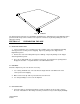
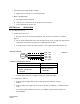
Fig. 1: LP4310 The LP4310 was designed for easy installation and maintenance. All maintenance and calibration work is performed from the top surface and does not require the removal of any decking or lifting the scale to adjust the leveling SECTION 2.0 PREPARATION FOR USE 2.1 RECEIVING INSPECTION 1. Upon receiving the scale, carefully inspect the condition of the crate including the banding and any protective covering used for shipping. Report any damage to the shipper and to Eagle Microsystems. 2.
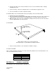
2. The hook-up cable to the read-out should not run close to other unshielded cables. Display instability may result. 3. For best accuracy, a flat, level, and rigid surface is recommended to support the scale. 5. The area should be accessible for periodic cleaning. 2.4 INSTALLING ( refer to LP4310 Outline & Interconnect Dwg. at the end of this manual) 1. Clean the site area of dirt and debris. 2. The scale should be oriented so that loading will be from the hinge side of the scale.
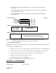
1. Inaccurate but repeatable weight readings: a. Adjust span on read-out (see instrument manual) 2. Blank or drifting display: a. Consult the instrument manual. b. Look for loose connection in hook-up cable at the instrument. c. Test for bad load cell (Section 4.1). SECTION 4.0 SERVICING 4.1 Checking the load cell. 1. Load Cell resistance test: a. Disconnect the load cells from the instrument and measure the resistance as shown in Figure 3. b.
d. An output signal greater than 5 millivolts indicates a zero shift caused by mechanical overload. e. If the output signal is between 5 and 15 millivolts, the load cells zero has shifted but will probably still continue to work. f. If the output signal is greater than 15 millivolts, the load cell should be replaced with a known good one.
30" x 30", 36" x 36", 42" x 42", and 48" x 48". WEIGHT: 33" x30" = 96 lbs, 36" x 36" = 115 lbs 42" x 42" = 135 lbs, 48" x 48" = 162 lbs CONSTRUCTION: Welded steel and formed plate. FINISH: Primer and Poline paint CAPACITY: 1000, 2000 and 4000 LB cap. SAFE OVERLOAD: 200% of Rated Capacity. ULTIMATE OVERLOAD: 400% of Rated Capacity. NOMINAL OUTPUT: 1.0 mV/V at full scale OPERATING ACCURACY: 0.5% of Capacity with repeatable load placement. REPEATABILITY: 0.