C3600P AND C7200P OPERATION INSTALLATION AND SERVICE MANUAL PRECISION TON CONTAINER SCALES EAGLE MICROSYSTEMS, INC. 366 Circle of Progress, Pottstown, PA 19464 610-323-2250 Phone - 610-323-0114 Fax e-mail: infomicrosys@verizon.
TABLE OF CONTENTS CONTENTS PAGE SECTION 1.0 DESCRIPTION..................................................................... 1 SECTION 2.0 PREPARATION FOR USE 3 2.1 RECEIVING INSPECTION 3 2.2 SHIPMENT 3 2.3 SITE SELECTION 3 2.4 INSTALLING 3 2.5 LEVELING 3 2.6 HOOK-UP CABLE 3 SECTION 3.0 OPERATION SECTION 4.0 TROUBLE SHOOTING SECTION 5.0 SERVICING 5.1 CHECKING THE CONNECTIONS 5.2 SERVICING THE LOAD CELL 5.3 CHECKING THE LOAD CELL 5.
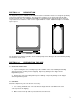
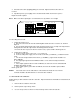
SECTION 1.0 DESCRIPTION The Eagle Microsystems C3600P and C7200P Precision Ton Container Scales are designed specifically for the water and wastewater industry. They incorporate 4 stainless steel shear beam load cells with integral overload stops. The C3600P and C7200P are supplied with the required amount of rollers for easy rotation of ton containers. Each scale is supplied with 15' of cable. Additional lengths are available upon request.
3. Use strong banding to secure scale in shipment. 2.3 SITE SELECTION 1. Extreme temperature variations may cause the scale to drift slightly off zero. Your precision ton container scale has temperature compensated load cells to minimize such effects. However, whenever possible, avoid placing your scale near air ducts, heating or cooling elements, doors opening to the outside, ect. to minimize temperature effects. 2.
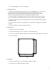
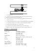
3. Using wrench to tighten all corners 2.6 HOOK-UP CABLE Figure 2 shows the wiring connections necessary to attach the platform to the read-out instrument. The color code and function are as noted. Consult read-out manual for the required information for its hookup. (Most scales are shipped with mating connector for easy hook-up to the instrument supplied) COLOR CODE BLACK WHITE RED GREEN YELLOW FIG. 2 SECTION 3.
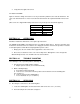
3. Check all connections by lightly pulling on each lead. Tighten terminal connections as needed. 4. If problem persists, press lightly on the circuit board itself and check meter response. Replace board if required. -S SH -S SH -E +S +S -S SH +S -E +E -SIG SHLD +SIG - -EXT + R1 +EXCT R1 +E R1 R1 -E R1 +E -S SH -E +S SJB4-S +E Note: Make sure when replacing the cover that the box is dry and the cover is tight. EAGLE MICROSYSTEMS FIG. 3 5.2 Checking the load cells. 1.
TC-SC 4. Set top frame aside. 5. Remove the 4 screws from Summing Box lid. Disconnect the wires of defective load cell being replaced. Gently pull cable out of the bottom frame. 6. Use hex wrenches to remove 2 socket head cap screws which secure load cell to frame. 7. Save the overload rod. 8. Install new load cell using 35 ft. lbs. torque to screws and fish wires back to the Summing Box. 9. Insert leads into terminal as before and tighten. Put lid on Summing Box and tighten. 10.
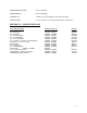
OPERATING ACCURACY: 0.1% of Capacity. REPEATABILITY: 0.02% of Capacity. LOAD CELLS: 4 stainless steel strain gage shear beams, 350 ohms. SIGNAL CABLE: 15' of 6 conductor color coded shielded cable. PVC jacket. SECTION 7.0 SPARE PARTS LIST PART DESCRIPTION S.S. Load Cell S.S. Load Cell S.S. Stop Rod S.S. 1/2-20 Hex Nut S.S. 1/2 Flat Washer S.S. 1/2 Lock Washer S.S. 1/2-20 X 1 3/4 S.H.C.S. Mounting bolt Shock Pad (2" X 1.5" X .75") Plastic Roller S.S. Roller Axle S.S.