
Specifications


SCR/SCRF Series Battery Charger
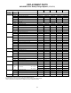
JD5022-00 Preventive Maintenance Procedure
MAINTENANCE DATE
PERFORMED BY
Step (standard features) Instructions Results
Clean battery charger
• All vents clean and open.
• Remove dust and debris from inside of unit.
¨ OK
¨ OK
Check all electrical
connections and wiring
• TB1 and TB2 connections all tight.
• Internal wiring connections tight, slip-on connectors fully seated. Wire
and lug insulation in good condition.
• Terminations at battery or bus are tight and corrosion free.
¨ OK
¨ OK
¨ OK
Check ac input voltage
• Measure at TB1-L1, TB1-L2 & TB1-L3 (3 Phase only) using ac
voltmeter. Value must be within +10%, -12% of nominal.
Input
Vac
Check dc output
voltage
• Measure at TB2(+) and TB2(-) using dc voltmeter. Value should agree
with front panel voltmeter within 2%, and must be correct values for
your battery. If the charger is using a temperature compensation probe,
see the curve in Section VII of user's manual to determine correct
battery voltage.
Float
Vdc
Equalize
Vdc
Check ripple voltage
• Measure at battery terminals using ac voltmeter set to milliVolts scale.
• Check against specification listed on charger's Data Nameplate.
Ripple
mVac
Exercise front panel
controls
• Switch from Float to Equalize, then back to Float.
¨ OK
• Verify front panel meters functional
¨ Volts OK
¨ Amps OK
• Verify adjustment capabilities of float and equalize potentiometers.
¨ Float OK
¨ Equalize OK
Check voltage settings
• Verify voltage setting per battery manufacturer recommendations.
• Utilize float and equalize potentiometers to make any required
adjustments. See Section IV of user's manual.
¨ Float OK
¨ Equalize OK
Final checks
• Close and latch front panel door.
• Restore charger to normal operation.
¨ OK
¨ OK
Step (optional features) Instructions Results
Check alarm settings
• See Section V of SCR/SCRF Series battery charger user’s manual for
calibration of alarms.
¨ HVDC OK
¨ LVDC OK
Combined Alarm Status
Monitor (CASM)
• See service instruction JD0036-00 for CASM alarm adjustments
• Test integrity of LEDs by pressing "lamp test" button on front panel.
¨ OK
Check integrity of
remote wiring
• Internal temperature compensation network wiring. See instruction
JA5022-00 and Section VII of user's manual.
• Temperature compensation remote probe. See instruction JA5022-00
and Section VII of user's manual.
¨ OK
¨ OK
Step (10-year repair) Instructions Results
Replace capacitors
• See supplied Parts Data Package report or standard replacement parts
table for battery charger manufacturer's part number of optional dc
filtering electrolytic capacitors (C1/C2).
• Order and replace capacitors
¨ OK