SCR/SCRF SERIES Operating and Service Instructions FLOAT BATTERY CHARGER THREE PHASE INPUT Eagle Eye Power Solutions 4230 N Oakland Ave #176, Milwaukee, WI 53211 Phone: 877-805-3377 | Web: www.eepowersolutions.
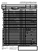
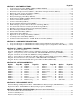
SCR/SCRF Series Battery Charger Factory-Configured Specifications JF0026-00 1 MODEL No. INPUT VOLTAGE Vac SERIAL No. FLOAT VOLTAGE Vdc EQUALIZE VOLTAGE Vdc SMART PART No. (items A-F req’d) Pos.
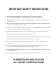
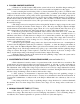
IMPORTANT SAFETY INSTRUCTIONS 1) Before using the battery charger, read all instruction and cautionary markings on: A) battery charger, B) battery, C) equipment connected to charger and battery 2) This manual contains important safety and operating instructions, and therefore should be filed for easy access. 3) Do not touch any insulated parts of the battery charger, especially the input and output connections, as there is the possibility of electric shock.
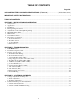
TABLE OF CONTENTS Page No. SCR/SCRF BATTERY CHARGER SPECIFICATIONS (JF0026-00).......................... (inside front cover) IMPORTANT SAFETY INSTRUCTIONS ................................................................................................ i TABLE OF CONTENTS......................................................................................................................ii-iii SECTION II - INSTALLATION AND OPERATION 1. Safety Notice ..........................................................
Page No. SECTION V - CUSTOMER OPTIONS 1. Ground Detection Circuits (EJ0088 / EJ0089 / EJ0094 / EJ0086) .................................................................. 14 2. AC Power Failure Alarm Relay (EJ0085) ....................................................................................................... 15 3. Three Phase AC Input Voltmeter (EJ0121) / Three Phase AC Input Ammeter (EJ0135)............................... 15 4. High and Low DC Voltage Alarm Relays (EJ0083) .........................
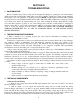
SECTION II INSTALLATION AND OPERATION 1. SAFETY NOTICE CAUTION! READ “IMPORTANT SAFETY INSTRUCTIONS” ON PAGE i. There are dangerous voltages within the battery charger cabinet! a. Only qualified personnel should attempt to adjust or service this equipment. b. Refer to instruction manual for service procedures and CAUTION notes. 2. APPLICATION Specifications: The silicon controlled rectifier is designed to maintain a system voltage within + or 0.
4. PLACING CHARGER IN SERVICE a. With the AC and DC breakers OFF and the system in float mode, install the charger making AC and DC connections, as described in Section II, 3, and in accord with local regulations as they apply. b. After connecting the lead from the positive (+) battery terminal to the positive (+) terminal on the charger and the lead from the negative (-) battery terminal to the (-) terminal on the charger, observe the voltmeter.
7. MAINTENANCE a. This charger is designed to require a minimum of maintenance. There are no rotating parts except in the optional timer and all components have a nominally indefinite life with no expected aging effect. It should be kept clean, dry and checked periodically to make sure all connections are tight. If necessary, dry air may be used to blow dust out of the interior.
. DESCRIPTION OF OPERATION There are four major sections of the SCR three-phase charger, which work together to produce stable, regulated, filtered output. The functions of these four sections may be described as follows. a. The Power Transformer (T1): This section includes T1 and its associated input protection. Its purpose is basically to supply an AC voltage of the proper magnitude and capacity to the rectifier section. It also supplies various other voltages used by the control unit and accessories.
SECTION III TROUBLESHOOTING 1. CAUTION NOTICE Before troubleshooting, always isolate and de-energize the charger by opening the AC circuit breaker (CB1) and the DC circuit breaker (CB2). This avoids the possibility of high short circuit current damaging the charger, tools, test equipment, or injuring personnel.
b. Power Transformer (T1) 1. With the AC and DC circuit breakers open or OFF, open the cabinet and carefully check the line voltage across line terminals on TB1, terminals (L1 to L2, L2 to L3 & L3 to L1). If no AC voltage is indicated, refer to Section III, 3, a, 1. Check the wiring connections to ascertain that the unit has the proper primary tap connections for the line voltage indicated. Turn on the AC circuit breaker (CB1). Check that the voltage at the primary is the same as that of the line.
2. Note that semiconductors usually short in pairs in bridge circuits, seldom as single units, and it is rare that all six semiconductors in a bridge are found defective. When diodes fail it usually is because of surge voltages. Therefore, surge suppressors (SS1, SS2, SS3 & SS4) should also be checked to determine that they are operative (refer to Section III, 3, d). f. SCR Diodes (SCR1/SCR2/SCR3) - also see Section III, 3, e 1.
4. Check square wave pattern at test points A1, A2 and A3. Note the 120-degree (5.5 mS) delay between the three patterns (scope synchronized to the 60 Hz AC line). If A1 pattern is missing, replace IC3. If A2 or A3 is missing, replace IC4. 5. Check ramp pattern at B1, B2 and B3. Compare with those shown in FIGURE 2. Note that the exact wave shape depends on the phase angle of SCR gates. The steeper the ramp the earlier in each half cycle the SCR is fired and the higher the output of the charger.
k. DC Ammeter (M1) 1. The charger DC ammeter is connected in series between the charger output and battery. If open it will indicate zero, or if shorted, it will also indicate zero. First be certain the connections are tight. If still no indication, turn CB1 and CB2 breakers to OFF, disconnect the charger ammeter (and/or shunt) and substitute a precision ammeter of suitable range.
SECTION IV SYSTEM ADJUSTMENTS 1. VOLTAGE ADJUSTMENTS AND RESPONSE When abnormal output voltage exists (or no output current is present), and the previous checks in Table A on page 27 “VOLTAGE ADJUST INEFFECTIVE” have been made without locating the fault, switch the AC breaker (CB1) to OFF. Switch the DC breaker (CB2) to OFF or disconnect the battery and proceed as follows: Check the battery with a portable voltmeter of one percent accuracy to insure that it is not higher than the rated float voltage.
b. Equalize Adjustment 1. Since the equalize adjustment will not affect the float voltage adjustment and requires a higher voltage it should always be made after the float voltage is determined. Use a portable voltmeter of one percent accuracy as in the float adjustment. Set switch (SW1) to “EQUALIZE”. Close the DC (battery) breaker (CB2). Set the AC breaker (CB1) to "ON". 2. In attempting to set the equalize voltage, one thing must be kept in mind.
2. CURRENT LIMIT RESPONSE AND ADJUSTMENT a. Checks and Adjustments: Make certain the charger leads are connected to the battery and that the panel voltmeter indicates the proper polarity. Switch the DC breaker (CB2) to "ON" and AC breaker (CB1) to "ON". The "AC ON" indicating light (DS1) should illuminate, indicating power has been applied.
SECTION V SCR/SCRF SERIES BATTERY CHARGER CUSTOMER OPTIONS The following pages describe customer options available in SCR/SCRF Series battery chargers. The text describes the basic operational philosophy and theory of operation. Block diagrams (or schematics) for these options are shown in Section VIII, in numerical order of the "EJ####" specification number. 1.
2. AC POWER FAILURE ALARM RELAY (EJ0085) - WITH OPTIONAL INDICATOR LIGHT Purpose: The purpose of this alarm is to notify the user that the AC input power to the battery charger has been interrupted. A front panel "AC FAILURE" lamp is optional for local indication. Relay contacts are provided for remote monitoring. Description: The principle of operation utilizes the normally closed contacts of an AC relay (K1). K1 is powered from the AC line at the primary of the transformer (T1).
If it is necessary to adjust the LVA threshold in the field, the user must load the battery bank and allow the battery voltage to drop while decreasing the float voltage adjustment to the desired cut-off potential. The LVA potentiometer is then adjusted so that the LVA relay is activated into the low voltage alarm condition. Note that there is a delay time, up to 30 seconds before the relay operates once the threshold voltage is reached.
7. EQUALIZE TIMERS Purpose: Equalize Timers are used to switch the charger into equalize charging mode for a set period of time, when required by the batteries. "FLOAT" and "EQUALIZE" indicating lights mounted on the instrument panel can be included with all timers to indicate the charging mode. There are three basic timers described below. These Equalize Timers replace the standard "FLOAT/EQUALIZE" switch (SW1) featured in the charger mainframe and referenced elsewhere in this manual. Descriptions: a.
8. COMMON ALARM BUZZER (EJ0123) Purpose: The Common Alarm Buzzer is a charger mounted audible alarm, which is activated when any of several different alarm circuits goes into an alarm state. Description: This circuit simply utilizes a set of contacts on each separate alarm relay. All of the contacts are wired in parallel and connect the audible alarm (AU1) to the battery voltage. If any set of contacts closes the alarm sounds. A switch (SW13) is provided to turn off the audible alarm if desired. 9.
12. ZERO-CENTER DC AMMETER FOR BATTERY/LOAD MONITORING (EJ0138) Purpose and Description: The zero-center dc ammeter (M7) lies within the negative return lead of the battery. A current-sensing shunt (SH2) is provided when the range is greater than 50 Amperes. M7 indicates the direction and amount of the battery current. Indication on the ammeter is to the right of center when the charger is charging the battery and to the left when the battery is furnishing current to the load (discharging). 13.
15. CURRENT LIMIT ALARM RELAY W/INDICATOR LIGHT (EJ0137) Purpose: The Current Limit Alarm provides an alarm signal whenever the battery charger output reaches the maximum limit set by the current limit circuit. An indicator lamp (DS24) mounted on the instrument panel also lights when the current limit alarm is activated. Description: The CLA PC Board assembly (A18) continually monitors the output of the current limit circuit on the charger control module (A1).
19. COMBINED ALARM STATUS MONITOR "CASM" PC BOARD ASSEMBLY (EJ0837) Note: Refer to the Drawing (EJ0837-XX) on page 49 for additional information. Purpose: The Combined Alarm-Status Monitor (CASM) provides a comprehensive, cost-effective method to monitor the integrity of the battery charger and the dc bus.
SECTION VI COMPONENT DESCRIPTION SCR/SCRF SERIES BATTERY CHARGER - THREE PHASE MAIN FRAME Circuit Symbol (Note 2) Spare? (Note 1) A1 B Component Description Three Phase Input Main Control Module PC Board XA1 Holder for Control Module PC Board (A1) SO1 Socket for Control Module PC Board (A1) A14 B Anode Firing Auxiliary Gate Drive Module PC Board (supplied with 175 Adc nominal dc output or greater) XA14 Holder for Gate Drive Module PC Board (A14) SO14 Socket for Gate Drive Module PC Board (A14
Circuit Symbol (Note 2) Spare? (Note 2) Component Description R1 Bleeder / Feedback Resistor R2 Voltage Divider Resistor R3 B R4 Float Adjustment Potentiometer Voltage Divider Resistor R5 B Equalize Adjustment Potentiometer SCR1 B Silicon-Controlled Rectifier (line 1) SCR2 B Silicon-Controlled Rectifier (line 2) SCR3 B Silicon-Controlled Rectifier (line 3) DC Ammeter Shunt (supplied with 50 Adc nominal dc output or greater) SH1 SS1 A, B DC Output Surge Suppressor SS2 A, B AC Inpu
COMPONENT DESCRIPTION SCR/SCRF SERIES BATTERY CHARGER OPTIONS - SINGLE/THREE PHASE NOTES: 1) "B" indicates recommended operating spare part 2) For component placement of circuit symbols, refer to SCR/SCRF Series Option Schematics in Section VIII starting on Page 34 3) For option replacement parts, refer to Section IX starting on Page 57 Option Number Ref.
Option Number Ref.
Option Number Ref.
PILOT LIGHT 27 5 8 9 6 9 HIGH OUTPUT RIPPLE DOES NOT EQUALIZE DIODE/SCR FAILURE SURGE SUPPRESSORS 1 10 11 11 PC BOARD REG.
29
30
31
32
Option Schematics 34
SCR/SCRF Series Battery Charger 35
Option Schematics 36
SCR/SCRF Series Battery Charger 37
Option Schematics 38
SCR/SCRF Series Battery Charger 39
Option Schematics 40
SCR/SCRF Series Battery Charger 43
Option Schematics 44
SCR/SCRF Series Battery Charger 45
Option Schematics 46
SCR/SCRF Series Battery Charger 47
ELECTRICAL RATINGS AND REPLACEMENT PARTS SCR/SCRF Series Battery Chargers (Three Phase Mainframe) PLEASE CONTACT YOUR SALES REPRESENTATIVE FOR DATA ON MODELS NOT LISTED. SCR/SCRF BATTERY CHARGER MODEL Enclosure Type AC INPUT CURRENT (MAXIMUM) 208Vac 240Vac 380Vac 480Vac 24V-50A 24V-75A 24V-100A 24V-125A 24V-150A 24V-175A 24V-200A 24V-250A Style-2 Style-2 Style-3 Style-3 Style-3 Style-3 Style-3 Style-3 6.8 5.9 3.7 3.0 10.2 8.8 5.6 4.4 14 12 7.4 5.9 17 15 9.3 7.4 21 18 12 8.
ELECTRICAL RATINGS AND REPLACEMENT PARTS SCR/SCRF Series Battery Chargers (Three Phase Mainframe) PLEASE CONTACT YOUR SALES REPRESENTATIVE FOR DATA ON MODELS NOT LISTED. SCR/SCRF BATTERY CHARGER MODEL Enclosure Type AC INPUT CURRENT (MAXIMUM) 208Vac 240Vac 380Vac 480Vac 48V-50A 48V-75A 48V-100A 48V-125A 48V-150A 48V-175A 48V-200A 48V-250A Style-2 Style-2 Style-3 Style-3 Style-3 Style-3 Style-3 Style-4 14 12 7.7 6.1 19 16 10.4 8.
ELECTRICAL RATINGS AND REPLACEMENT PARTS SCR/SCRF Series Battery Chargers (Three Phase Mainframe) PLEASE CONTACT YOUR SALES REPRESENTATIVE FOR DATA ON MODELS NOT LISTED. SCR/SCRF BATTERY CHARGER MODEL 130V-25A Enclosure Type AC INPUT CURRENT (MAXIMUM) 208Vac 240Vac 380Vac 480Vac 130V-35A 130V-50A 130V-75A 130V-100A 130V-125A 130V-150A 130V-200A 130V-250A Style-2 Style-2 Style-3 Style-3 Style-3 Style-3 Style-4 Style-4 Style-5 18 16 9.6 7.
ELECTRICAL RATINGS AND REPLACEMENT PARTS SCR/SCRF Series Battery Chargers (Three Phase Mainframe) PLEASE CONTACT YOUR SALES REPRESENTATIVE FOR DATA ON MODELS NOT LISTED.
REPLACEMENT PARTS SCR/SCRF Series Battery Charger Options (1PH/3PH) BATTERY CHARGER NOMINAL OUTPUT OPTION NUMBER CIRCUIT SYMBOL EJ0083 A2 EJ0084 EJ0086 HLVA Alarm Control PC Board RA0001-01 RA0001-01 RA0001-01 RA0001-06 RA0001-06 RA0001-06 RA0001-06 RA0001-06 R57 Power Supply Ballast Resistor n/a RJ0028-36 RJ0015-33 RJ0022-04 RJ0022-05 n/a n/a RJ0028-24 RJ0035-42 RJ0008-13 R75 DS3 Ballast Resistor SO2 Plug for A2 DS5 Float Indicating Light RA0001-05 RA0001-05 RA0001-05 RA
REPLACEMENT PARTS SCR/SCRF Series Battery Charger Options (1PH/3PH) BATTERY CHARGER NOMINAL OUTPUT OPTION NUMBER CIRCUIT SYMBOL EJ0120 A5 DS10 EJ0131 EJ0133 130 Vdc 260 Vdc MANUFACTURER'S PART NO.
REPLACEMENT PARTS SCR/SCRF Series Battery Charger Options (1PH/3PH) BATTERY CHARGER NOMINAL OUTPUT OPTION NUMBER CIRCUIT SYMBOL EJ0134 CT1 M3 DESCRIPTION AC Current Transformer AC Ammeter EJ0135 CT1 - CT3 M3 EJ0137 12 Vdc AC Current Transformer AC Ammeter 24 Vdc 48 Vdc 130 Vdc 260 Vdc MANUFACTURER'S PART NO.
REPLACEMENT PARTS SCR/SCRF Series Battery Charger Options (1PH/3PH) BATTERY CHARGER NOMINAL OUTPUT 12 Vdc 24 Vdc 48 Vdc 130 Vdc 260 Vdc OPTION NUMBER CIRCUIT SYMBOL EJ0141 AU1 Common Alarm Buzzer RA0004-00 RA0004-00 RA0004-00 RA0004-00 RA0004-00 EJ0143 EJ0155 K8 Common Alarm Relay RF0010-01 RF0010-03 RF0010-03 RF0010-06 RF0010-06 Ballast Resistor for AU1 n/a n/a n/a RJ0015-46 RJ0035-48 R63 Ballast Resistor for K8 n/a n/a RJ0015-33 n/a RJ0015-48 SW13 Buzzer ON/OFF Switc
REPLACEMENT PARTS SCR/SCRF Series Battery Charger Options (1PH/3PH) BATTERY CHARGER NOMINAL OUTPUT OPTION NUMBER EJ0837 EJ0862 EJ0869 CIRCUIT SYMBOL A24 24 Vdc EN0014-82 EN0014-83 EN0014-82 EN0014-83 EN0014-82 EN0014-83 EN0014-82 EN0014-83 EN0014-82 EN0014-83 RA0008-00 RA0008-00 RA0008-00 RA0008-00 RA0008-00 DESCRIPTION 48 Vdc 130 Vdc 260 Vdc MANUFACTURER'S PART NO.
SECTION X MANUAL SPECIFICATIONS DOCUMENT NUMBER: The internal text and graphics contained within this manual are controlled by the battery charger manufacturer's internal part number (JA5036-00). Revision level and dates for this part are listed below. These controls supercede all other available dates. The first two and last two pages of this manual are reserved for company-specific front and back cover artwork.
SCR/SCRF Series Battery Charger Preventive Maintenance Procedure JD5022-00 MAINTENANCE DATE PERFORMED BY Step (standard features) Clean battery charger Instructions • All vents clean and open. • Remove dust and debris from inside of unit. Check all electrical connections and wiring Check ac input voltage Check dc output voltage Check ripple voltage • TB1 and TB2 connections all tight. • Internal wiring connections tight, slip-on connectors fully seated. Wire and lug insulation in good condition.
SCR/SCRF SERIES BASIC START-UP AND SHUT DOWN INSTRUCTIONS START UP Switch "ON" DC Circuit Breaker. Switch "ON" AC Circuit Breaker. SHUT DOWN Switch "OFF" AC Circuit Breaker. DC Circuit Breaker may be left "ON" or "OFF". NOTE If Circuit Breakers are not installed, use external devices to remove power to and from the battery charger. WARNING AC and DC Circuit Breakers do not remove power to some components within the battery charger enclosure.