Pub. 988-0143-651 www.eaglesonar.
Copyright © 2002 Eagle Electronics All rights reserved. Eagle® is a registered trademark of Eagle Electronics Marine-Tex is a trademark of Illinois Tool Works Inc. Eagle Electronics may find it necessary to change or end our policies, regulations, and special offers at any time. We reserve the right to do so without notice. All features and specifications subject to change without notice. All screens in this manual are simulated. For free owner's manuals and other information, visit our web site: www.
Table of Contents Introduction .................................................................................. 1 Capabilities and Specifications .................................................... 1 Installation.................................................................................. 2 Transducer Installation ............................................................... 2 selecting a transducer location.................................................. 3 shoot-thru-hull vs. transom mounting..
System Setup .............................................................................38 Display backlights .....................................................................38 Display contrast ........................................................................39 Depth units of measure.............................................................39 Temperature units of measure .................................................40 Speed and distance log units of measure .............................
Introduction Thank you for buying an Eagle sonar! Your unit is a high-quality sonar designed for both professional and novice fishermen. All Eagle sonars have an automatic mode that finds and displays the bottom, fish, underwater structure and more – right out of the box. All you have to do is press the on (PWR) key. However, if you want to fine-tune your unit, press the MENU UP key.
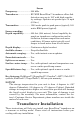
Sonar Frequency:...................... 200 kHz. Transducer: .................... BV-WSX BroadView transducer offers fish detection area up to 150º with high sensitivity settings. Operates at speeds up to 70 mph (61 kts.) Transmitter: ................... 1500 watts peak-to-peak power (typical); 188 watts RMS power (typical). Sonar sounding Depth capability:........... 800 feet (244 meters). Actual capability depends on transducer configuration and installation, bottom composition and water conditions.
Your BroadView transducer comes packaged with a trolling motor mount that uses a plastic bracket with an adjustable strap. It also comes with a bracket for mounting it to the transom of your boat. These are both "kick-up" mounting brackets. They help prevent damage if the transducer strikes an object while the boat is moving. If the transducer does "kick-up," the bracket can easily be pushed back into place without tools. Read these instructions carefully before attempting the installation.
4. If possible, route the transducer cable away from other wiring on the boat. Electrical noise from engine wiring, bilge pumps and aerators can be displayed on the sonar's screen. Use caution when routing the transducer cable around these wires. CAUTION: Clamp the transducer cable to transom near the transducer. This will help prevent the transducer from entering the boat if it is knocked off at high speed.
If you cruise or fish around lots of structure and cover, your transducer may be frequently kicking up from object strikes. If you wish, you may move the transducer a little higher for more protection. There are two extremes you should avoid. Never let the edge of the mounting bracket extend below the bottom of the hull. Never let the bottom – the face – of the transducer rise above the bottom of the hull. Shoot-thru-hull vs.
Ratchets Insert bolt and check transducer position on transom. 3. Assembling the transducer. Once you determine the correct position for the ratchets, assemble the transducer as shown in the following figure. Don't tighten the lock nut at this time. Nut Metal washer Rubber washers Metal washer Bolt Assemble transducer and bracket. 4. Drilling mounting holes. Hold the transducer and bracket assembly against the transom. The transducer should be roughly parallel to the ground.
Transom Transom Position transducer mount on transom and mark mounting holes. Side view shown at left and seen from above at right. 5. Attaching transducer to transom. Remove the transducer from the bracket and re-assemble it with the cable passing through the bracket over the bolt as shown in the following figures. Route cable over bolt and through bracket. Side view shown at left and seen from above at right. Attach the transducer to the transom.
over tighten the lock nut! If you do, the transducer won't "kick-up" if it strikes an object in the water. Bottom of hull Deep-"vee" hull Flat-bottom hull Align transducer centerline with hull bottom and attach to transom. 6. Route the transducer cable through or over the transom to the sonar unit. Make sure to leave some slack in the cable at the transducer. If possible, route the transducer cable away from other wiring on the boat.
Internal tooth washer Bolt TMB-S bracket Nut Flat washer Attach motor mounting bracket to transducer. 2. Slide the adjustable strap supplied with the TMB-S through the slot in the transducer bracket and wrap it around the trolling motor. Position the transducer to aim straight down when the motor is in the water. Tighten the strap securely. 3. Route the transducer cable alongside the trolling motor shaft. Use plastic ties (not included) to attach the transducer cable to the trolling motor shaft.
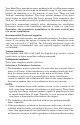
Partial fish arches Transducer aimed too far back Transducer aimed too far forward Full fish arch Proper transducer angle Transducer angles and their effects on fish arches. If the arch slopes up – but not back down – then the front of the transducer is too high and needs to be lowered. If only the back half of the arch is printed, then the nose of the transducer is angled too far down and needs to be raised. NOTE: Periodically wash the transducer's face with soap and water to remove any oil film.
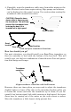
Temp sensor display, from an external TS-1X, or combo speed/temp sensor Full Chart page showing dual temperature display. See the following charts for sample sensor combinations and cable connections. TriFinder 2 rear view 3-amp fuse 12-volt battery Power/sensor cable TS-1X temperature sensor Transducer with no temperature sensor TriFinder 2 with external temperature sensor. This unit has a power cable with a connector for sensors.
TriFinder 2 rear view 3-amp fuse 12-volt battery Power/sensor cable Transducer with no temperature sensor ST-TX combination speed-temp sensor TriFinder 2 with external combination speed and temperature sensor. Transducers with built-in temp sensors are not compatible with TriFinder 2 units. Speed Sensor Installation If you wish to purchase an optional sensor for your unit, refer to the accessory ordering information inside the back cover of this manual.
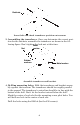
If the base of the transom has a radius, fill the gap between the transom and the sensor with the caulking compound. This will help ensure a smooth water flow. Good location Stern view showing good location for mounting sensor on transom. Transom Bottom of hull Bottom of hull Speed sensor mounting configuration: side view (left) and rear view (right.) Route the sensor's cable through or over the transom to the sonar unit.
Red wire 3 amp fuse Black wire To unit 12 volt battery Power connections for TriFinder 2. If possible, keep the power cable away from other boat wiring, especially the engine's wires. This will provide the best isolation from electrical noise. If the cable is not long enough, splice #18 gauge wire onto it. The power cable has two wires, red and black. Red is the positive lead, black is negative or ground.
121 [4.76] Top 47 [1.85] Hole diameter 3.5 [0.14] In-Dash Template Millimeters [Inches] 112 [4.40] Cut on line ALWAYS VERIFY DIMENSIONS R 6.35 [0.25] 119 [4.68] In-dash mounting template for TriFinder 2, showing dimensions. NOTE: The figure above is not printed to scale. A scaled template is available for free download from our web site, www.eaglesonar.com. If you use the supplied gimbal bracket, you may be interested in the optional GBSA-1 swivel bracket kit.
61.3 [2.42] 136 [5.35] 23.8 [0.94] 147.4 [5.80] 132 [5.20] Millimeter [Inch] 66 [2.60] Front view (left) and side view (right) showing dimensions of the TriFinder sonar unit when mounted on gimbal bracket. Drill a 1-inch (25.4 mm) hole in the dash for the power and transducer cables. The best location for this hole is immediately under the gimbal bracket location. This way, the bracket can be installed so that it covers the hole, holds the cables in position and results in a neat installation.
of the bracket base firmly against the cables, thus pinning them in place against the side of the hole. Finally, fasten the bracket to the dash. Attach the unit to the gimbal bracket using the supplied gimbal knobs and washers. Slide the rubber washers onto the gimbal knobs then loosely screw the knobs into their sockets. Slide the unit into the bracket with the rubber washers to the outside of the bracket arms.
NOTE: Though the PPP-10 will give you the liberty of a portable sonar unit, the portable transducer that comes with it is not a BroadView transducer. While using the portable transducer you will not get the extra sonar information necessary to use TargetTrack. Operation KEYBOARD BASICS The unit sounds a tone when you press any key. This tells you the unit has accepted a command.
2. MENU UP (menu up) 3. MENU DOWN (menu down) These keys appears in the manual text as MENU UP or MENU DOWN. (In some units, the keys may appear as MENU FWD or MENU REV, respectively.) Most of the time, the instructions require you to press either menu key, so the text simply uses the word MENU. Usually, when we say MENU, you can simply press the MENU UP key for consistency. This sonar unit has many features that are accessed with the menu keys.
Menus change depending on the mode the unit is in. Messages may appear in menu boxes or new menus can appear, depending on previous selections. DISPLAY – Opening Screen The lights flash for about 10 seconds when the unit is turned on. The backlight menu first appears on the screen. To turn the lights on, press UP ARROW. If you don't press a key, the menu will disappear after a few seconds. If you don't want to wait, press PWR to clear the menus from the screen.
Chart menu. Chart is running or scrolling normally at left. Chart is stopped at right, and "Stopped" warning message appears. SCREEN DISPLAY MODES or PAGES The TriFinder 2 has three screen display modes, or "Pages:" Full Chart page, Split Chart page and Large Digital page. The Page menu lets you select from three display modes, or pages. To switch from one page to another page, press MENU until the PAGE menu appears. Press UP ARROW or DOWN ARROW to select the desired page.
Depth scales on the right side of the screen makes it easy to determine the depth of fish, structure, and other targets. The line at the top of the screen represents the surface. The bottom depth (as determined by the digital sonar) shows in the upper left corner. If an optional speed or temperature sensor is connected, digital displays for speed and/or temperature will also be shown. Full Chart page, showing digital depth at top and speed at bottom.
NOTE: Temperature, speed, and distance require optional temperature or speed sensors. Large Digital page. RANGE When turned on for the first time, the unit automatically adjusts the depth range according to water conditions. It always keeps the bottom displayed in the lower portion of the screen. You can over-ride the automatic range control and manually select a range. To do this, press MENU until the RANGE menu appears. Use the arrow keys to select the desired range.
ZOOM The zoom feature enlarges all echoes on the screen. The 2X zoom doubles the size of the echoes on the display; the 4x zoom quadruples the echo size. To zoom the display, first press the MENU key until the ZOOM menu appears. Use the arrow keys to select either 2X or 4X zoom, then press PWR to clear the menu. Zoom screen, showing Zoom menu and the 2X zoom indicator at the top right of the screen.
ter column from 13 feet to about 39 feet, with 25 feet still in the middle of the screen. Important Tip: Your unit has the handy ability to quickly zoom in on any portion of the water column with just the touch of an arrow key. The Zoom Pan feature lets you rapidly move the zoomed area up and down to different depths. By "pointing" your zoom at different portions of the chart as it scrolls, you can get a good, close-up look at structure or cover below you.
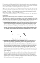
Fig. 1 Fig. 2 Fig. 3 Fig. 4 Bait school Thermocline with fish Fish arches These figures show results of different sensitivity levels on the same location. Fig. 1: Sensitivity at 87 percent, determined by Auto Sensitivity. Typical of full auto mode. Fig. 2: Sensitivity set at 50 percent. Fig. 3: Sensitivity set at 20 percent. Fig. 4: Sensitivity set at 100 percent. You can change the sensitivity level whether you are in Auto Sensitivity mode or Manual Sensitivity mode.
100 percent, but the unit will limit your minimum setting. This prevents you from turning sensitivity down too low to allow automatic bottom tracking. When you change the setting with auto turned on, the unit will continue to track the bottom and make minor adjustments to the sensitivity level, with a bias toward the setting you selected. Adjusting sensitivity in Manual Sensitivity Mode is similar to driving a car without cruise control — you have complete manual control of the car's speed.
NOTE: If you want to change the sensitivity in Manual Mode, first turn off Auto Sensitivity: press MENU until the SENSITIVITY AUTOMATIC/MANUAL menu appears. Press DOWN ARROW to select MANUAL, then press PWR to clear the menu. To adjust the sensitivity, follow the same steps used for adjusting sensitivity in auto mode above. ® GRAYLINE Grayline lets you distinguish between strong and weak echoes. It "paints" gray on targets that are stronger than a preset value.
Press UP ARROW to increase the level or press DOWN ARROW to decrease it. The percentage of Grayline in use shows in this menu. Echoes scrolling onto the screen will also show the effects of the Grayline change. If you reach the maximum or minimum level, a tone sounds alerting you to the limits. Press PWR to clear the menu. FISH I.D. The Fish I.D. feature identifies targets that meet certain conditions as fish.
You may see Fish I.D. symbols on the screen when actually, there are no fish. The reverse is also true — Fish I.D. can actually miss fish that are present. Does that mean Fish I.D. is broken? No — the feature is simply interpreting sonar returns in a specific way to help take some of the work out of reading the screen. Remember: Fish I.D. is one of the many tools we provide so you can analyze your sonar returns for maximum fish finding information.
TARGETTRACK The TriFinder 2 has the unique ability to "see" targets not only straight down, but also to the right and left, thanks to the BroadView™ transducer. The TargetTrack feature shows you if the target is to the left, right or straight down. The BroadView transducer has three elements: left, right and down. The TriFinder uses all three elements to display targets between the surface and the bottom. Targets are shown as Fish I.D. symbols.
Target Track option in Fish ID menu. FISHREVEAL When displaying actual sonar returns, the FishReveal feature helps show fish targets hidden by surface clutter, thermoclines, weed beds and other cover with 10 levels of gray tones. Normal operation (with FishReveal turned off) shows the weakest echoes as black and the strongest in light gray. Since all weak echoes are black, fish arches show boldly against the white background.
In Inverted FishReveal mode, the weakest echoes are black and the strongest echoes are white. Again, echoes in between vary in gray in proportion to their signal strength. In all modes, the Grayline control determines the range for black to white. At left, standard FishReveal mode. Right, Inverted Fish Reveal mode. To turn FishReveal on, press MENU DOWN until CHART SETUP appears, then press UP ARROW. Press MENU DOWN until CHART MODE appears. Press DOWN ARROW to select the desired FishReveal mode.
sonar signal cone, the image appears on the screen as a long line instead of a fish arch. Reducing the chart speed may result in a shorter line that more closely resembles a regular fish return. At right, Scroll Speed menu at default 60 percent setting. At left, Scroll Speed menu, with unit set to HyperScroll mode. If you are running fast, try a HyperScroll setting of 80 to 100 percent. When using HyperScroll, you may also need to manually decrease the sensitivity for best performance.
over the face of the transducer, even vibration from the engine. In all cases, noise can produce unwanted marks on the display. The ASP noise rejection feature is especially useful because it typically lets you operate the boat at all speeds without adjusting the sensitivity or other controls. Noise Reject menu. The ASP feature has four settings — Off, Low, Medium and High. When first turned on, noise rejection is set on low. If you have high noise levels, try using the medium or high ASP setting.
To turn off the fish alarm without turning off fish symbols, press MENU DOWN until FISH ALARM appears. Press DOWN ARROW to select OFF, then press PWR to clear the menu. Repeat the above steps to turn the alarm back on, but press UP ARROW to select ON before clearing the menu. Fish Alarm menu. Depth Alarms The depth alarms are triggered only by the bottom signal. No other echoes will activate these alarms. The depth alarms consist of a shallow and a deep alarm.
DOWN ARROW to decrease it. The number in the shallow alarm’s menu box shows the current shallow alarm setting. When the number reaches the desired setting, press PWR to clear the menu. When the bottom depth goes shallower than the alarm’s setting, an alarm tone sounds and a message box appears on the screen. Press UP ARROW to silence the alarm. This turns the alarm sound off until the shallow alarm is triggered again. To turn the alarm off, press MENU DOWN repeatedly until SHALLOW ALARM appears.
SYSTEM SETUP To customize the display, press MENU DOWN until the SYSTEM SETUP menu appears, then press UP ARROW. The display contrast, units of measure, temperature, and system information screens are all under this menu. The Contrast menu appears first. Press the MENU UP or MENU DOWN keys to cycle through the menus. When you're finished, press the PWR key to clear the menus. System Setup menu. DISPLAY ADJUSTMENTS BACKLIGHTS The display is backlit for night use.
DISPLAY CONTRAST The unit’s display contrast is adjustable to suit different lighting conditions. This will help you see the screen from different angles or at various times of the day. The default setting is 50 percent. To adjust the contrast, press MENU DOWN until the SYSTEM menu appears, press UP ARROW, and the CONTRAST menu appears. To decrease screen contrast, press the DOWN ARROW key. Press the UP ARROW key to increase screen contrast.
TEMPERATURE UNITS OF MEASURE This unit can show the temperature (if a temperature sensor is attached) in degrees Fahrenheit or Celsius. To change the unit of measure, press MENU DOWN until the SYSTEM menu appears. Press UP ARROW, then press MENU until the TEMPERATURE menu appears. Use the arrow keys to select the measurement unit, then press PWR to clear the menu. Temperature unit of measure menu.
RESET DISTANCE LOG You can reset the distance log to zero with this command. Press MENU DOWN until SYSTEM appears, then press UP ARROW. Press MENU until the RESET LOG menu appears. Press UP ARROW and the log returns to zero. Press PWR to clear the menu. Reset Log menu. PRESET UNIT (reset all options) This command is used to reset all features, options and settings to their original factory defaults.
SYSTEM INFO To show the operating software system information, press MENU DOWN until the SYSTEM menu appears, then press UP ARROW. Press MENU DOWN until the SYSTEM INFO screen appears. Press PWR to clear the screen. System Info screen. SIMULATOR This unit has a built-in simulator that shows a simulated bottom signal with fish signals. This lets you practice with the unit as if you were on the water; all features and functions of the unit are usable.
NOTE: If you turn on your unit before attaching a transducer, it may enter a demo mode. The words "demo mode" flash on the bottom of the screen and a sonar chart plays much like the Simulator feature. Unlike the simulator, the demo mode is for demonstration only, and will automatically stop as soon as you turn on the unit with a transducer attached. The simulator will continue to function normally. CHART SETUP The Chart Setup menu lets you further customize the display.
detail seen on the sonar chart. Try this command only if you are in deep water, traveling at high speed, and notice a reduction in detail on the sonar chart. When Limit Search is turned on, the digital sonar will limit its search for the bottom to the depth range you have set for the sonar chart. NOTE: Turning Limit Search on can cause the digital sonar to lose the bottom in some situations. The digital depth will flash if that occurs.
Menus for changing digital number size. To change any of these options, press MENU DOWN until CHART SETUP appears, then press UP ARROW. Use the MENU keys to cycle through the list and display the desired menu, then use the ARROW keys to select the desired number size or turn the numbers off. Press the PWR key to clear the menus. SCALES The depth scale between the upper and lower limit on the right side of the screen can be turned on or off. The default is on.
Troubleshooting If your unit is not working, or if you need technical help, please use the following troubleshooting section before contacting the factory customer service department. It may save you the trouble of returning your unit for repair. For contact information, refer to the last page, just inside the back cover of this manual. Unit won't turn on: 1. Check the power cable's connection at the unit. Also check the wiring. 2. Make certain the power cable is wired properly.
noise rejection feature. This can cause the unit to eliminate weaker signals such as fish or even structure from the display. 3. The water may be deeper than the sonar's ability to find the bottom. If the sonar can't find the bottom signal while it's in the automatic mode, the digital sonar display will flash continuously. It may change the range to limits far greater than the water you are in.
NOISE A major cause of sonar problems is electrical noise. This usually appears on the sonar's display as random patterns of dots or lines. In severe cases, it can completely cover the screen with black dots, or cause the unit operate erratically, or not at all. To eliminate or minimize the effects of electrical noise, first try to determine the cause. With the boat at rest in the water, the first thing you should do is turn all electrical equipment on the boat off. Make sure the engine is also off.
EAGLE ELECTRONICS FULL ONE-YEAR WARRANTY "We," "our," or "us" refers to EAGLE ELECTRONICS, a division of LEI, the manufacturer of this product. "You" or "your" refers to the first person who purchases this product as a consumer item for personal, family, or household use. We warrant this product against defects or malfunctions in materials and workmanship, and against failure to conform to this product's written specifications, all for one (1) year from the date of original purchase by you.
How to Obtain Service… …in the USA: We back your investment in quality products with quick, expert service and genuine Eagle replacement parts. If you're in the United States and you have technical, return or repair questions, please contact the Factory Customer Service Department. Before any product can be returned, you must call customer service to determine if a return is necessary. Many times, customer service can resolve your problem over the phone without sending your product to the factory.
Accessory Ordering Information for all countries To order Eagle accessories such as power cables or transducers, please contact: 1) Your local marine dealer or consumer electronics store. Most quality dealers that handle marine electronic equipment or other consumer electronics should be able to assist you with these items. To locate an Eagle dealer near you, visit the web site, www.eaglesonar.com, and look for the Dealer Locator. Or, consult your telephone directory for listings. 2) U.S.
Visit our web site: www.eaglesonar.com Eagle Pub.