Pub. 988-0143-681 www.eaglesonar.
Copyright © 2002 Eagle Electronics All rights reserved. Eagle® is a registered trademark of Eagle Electronics Marine-Tex is a trademark of Illinois Tool Works Inc. Points of Interest Data in this unit are by infoUSA, copyright 2001-2002, All Rights Reserved. infoUSA is a trademark of infoUSA, Inc. eXitSource Database, copyright 2001-2002 Zenrin Co. Ltd. Exit Authority and eXitSource are trademarks of Zenrin Co. Ltd.
Table of Contents Section 1: Read Me First!......................................................... 1 Capabilities and Specifications: IntelliMap 320 ...................... 2 How Eagle GPS Works ................................................................. 4 How To Use This Manual: Typographical Conventions.............. 8 Section 2: Installation & Accessories .................................. 11 GPS Antenna/Receiver Module Installation.............................. 11 Power Connections..............
Create Icon On Map................................................................ 54 Create Icon At Current Position ............................................ 54 Delete an Icon ......................................................................... 54 Navigate To an Icon ................................................................ 55 Routes.......................................................................................... 55 Create and Save a Route ..........................................
Map Datum Selection ................................................................. 77 Map Detail Category Selection................................................... 77 Map Orientation ......................................................................... 78 Navionics Charts....................................................................... 79 Pop-Up Help ................................................................................ 85 Position Pinning..........................................
WARNING! A CAREFUL NAVIGATOR NEVER RELIES ON ONLY ONE METHOD TO OBTAIN POSITION INFORMATION. CAUTION When showing navigation data to a position (waypoint), a GPS unit will show the shortest, most direct path to the waypoint. It provides navigation data to the waypoint regardless of obstructions.
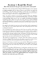
Section 1: Read Me First! How this manual can get you out on the road, fast! Welcome to the exciting world of digital GPS! We know you're anxious to begin navigating, but we have a favor to ask. Before you grab the IntelliMap 320 and begin installing it, please give us a moment or two to explain how our manual can help you get the best performance from your compact, wide-screen, mapping GPS receiver. First, we want to thank you for buying an Eagle GPS unit.
Section 3 contains short, easy-to-scan GPS lessons that follow one another in chronological order. They're all you'll need to know to find your way on the water or in the wilderness quickly. After you've learned the basics (or if you already have some GPS experience), you may want to try out some of the IntelliMap 320's many advanced navigation features. That brings us to Section 4, Advanced GPS Operations. This section contains the rest of the unit's GPS command functions, organized in alphabetical order.
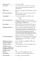
Input power:................... 10 to 15 volts DC. Case size:......................... 5.4" H x 6.9" W x 3.4" D (13.8 x 17.6 x 8.6 cm); sealed and waterproof; suitable for saltwater use. MMC slots: ...................... One with waterproof door (SD card compatible). Back-up memory: .......... Built-in memory stores sonar records and GPS data for decades. Languages:...................... 10; menu languages selectable by user. GPS Receiver/antenna: .........
NOTE: The above memory capacities refer only to the IntelliMap 320's onboard memory. The amount of GPS data you can record and save for recall later is only limited by the number of MMC cards you have. NOTICE! The storage temperature range for your IntelliMap 320 is from -4 degrees to +167 degrees Fahrenheit (-20 degrees to +75 degrees Celsius). Extended storage in temperatures higher or lower than specified will damage the liquid crystal display in your unit.
The background map is suitable for many navigation chores, but for maximum accuracy and much more detail, you need our optional mapmaking software, MapCreate 6. Some unit features — such as searching for businesses and addresses — won't work without a custom MapCreate map. There is so much detail in our background map (and even more in MapCreate) that we'll describe their contents and differences in Section 6, Basic GPS Operations, on page 21.
Introduction to GPS and WAAS Well, now you know the basics of how the unit does its work. You might be ready to jump ahead to Section 2, Installation & Accessories, on page 11, so you can mount your IntelliMap 320 and plug in the power. Or you might want to see how our text formatting makes the manual tutorials easy to skim. If that's the case, move on to "How to Use This Manual" on page 8.
determine a position. This is called a 2D fix. It takes four satellites to determine both position and elevation (your height above sea level — also called altitude). This is called a 3D fix. Remember, the unit must have a clear view of the satellites in order to receive their signals. Unlike radio or television signals, GPS works at very high frequencies. These signals can be easily blocked by trees, buildings, an automobile roof, even your body.
receiver is only a tool. Always have another method of navigation available, such as a map or chart and a compass. Also remember that this unit will always show navigation information in the shortest line from your present position to a waypoint, regardless of terrain! It only calculates position, it can’t know what’s between you and your destination, for example. It’s up to you to safely navigate around obstacles, no matter how you’re using this product.
3. You are asked to wait while it converts the trail into a route. 4. The wait message disappears and the IntelliMap 320 begins showing navigation information along the trail. Now, begin moving and follow your IntelliMap 320. Translated into complete English, step 1 above would mean: "Start on the Map Page. Press the Menu key twice. Next, repeatedly press (or press and hold) the down arrow key to scroll down the menu and select (highlight) the My Trails menu command. Finally, press the Enter key.
Notes 10
Section 2: Installation & Accessories Preparations You can install the GPS system in some other order if you prefer, but we recommend this installation sequence: Caution: You should read over this entire installation section before drilling any holes in your vehicle or vessel! 1. Determine the approximate location for the GPS unit, so you can plan how and where to route the cables for the antenna and power. This will help you make sure you have enough cable length for the desired configuration. 2.
You need to select an antenna installation location that has a clear, unobstructed view of the sky. After the module is installed, route the cable to the unit, plug it in the center socket on the back and your system is ready to use. See the module's instruction sheet, publication part number 988-0148-37, for complete installation directions. In an automobile, you may achieve good results by simply placing the external antenna on the top of the dash, at the base of the windshield.
For example, if you have to extend the power cable to the battery or power buss, attach one end of the fuse holder directly to the battery or power buss. This will protect both the unit and the power cable in the event of a short. It uses a 3-amp fuse. To unit Optional power off switch for saltwater installations Red wire with 3 amp fuse Black wire 12 volt battery Power connections for the IntelliMap 320 GPS unit.
Bracket Installation Mount the IntelliMap 320 in any convenient location, provided there is clearance behind the unit when it's tilted for the best viewing angle. You should also make sure there is enough room behind the IntelliMap 320 to attach the power and GPS antenna/receiver module cables. (A drawing on the next page shows the dimensions of a gimbal-mounted IntelliMap 320.) Holes in the bracket's base allow wood screw or through-bolt mounting.
72.9 [2.87] 23.4 [0.92] 173.9 [6.85] 137.9 [5.43] 157.9 [6.22] 56.9 [2.24] Millimeter [Inch] Front view (left) and side view (right) showing dimensions of the IntelliMap 320 when mounted on gimbal bracket. After drilling the hole, pass the antenna connector up through the hole from under the dash. Pass the power cable's bare-wire end down though the hole from the top. If you wish, you can fill in the hole around the cables with a good marine caulking compound.
146.5 [5.76] Top R 7.9 [0.31] In-Dash Template 113.5 [4.46] Millimeters [Inches] ALWAYS VERIFY DIMENSIONS In-dash mounting template for the IntelliMap 320, showing dimensions. NOTE: The figure above is not printed to scale. A scaled template (FM-5 In-Dash Adapter Kit instructions) is available for free download from our web site, www.eaglegps.com. Portable Installation Like many Eagle products, the IntelliMap 320 is capable of portable operation by using the optional PPP-13 portable power pack.
"D" cell battery Install batteries in power pack battery adapter. MMC or SDC Memory Card Installation Your IntelliMap 320 uses a MultiMedia Card to store information, such as custom maps, waypoints, trails and other GPS data. The unit can also use Secure Digital Cards (SD card or SDC) to store data. NOTE: Throughout this manual, we will use the term MMC, but just remember that your unit can use an MMC or SDC to store data.
MMC groove for card removal Thumb screw Insert card face up, this way Memory card compartment with a 16 MB MMC card installed. To remove an MMC 1. Open the card compartment door by unscrewing the thumb screw. The screw should only be finger tight. If it was over-tightened, use a thumbnail, a coin or a screwdriver to open the door. 2. Use a thumbnail or fingernail to grab the groove in the bottom of the MMC. See the figure above for the groove location. 3. Drag the MMC from the slot.
MapCreate™ 6 CD-ROM, left; MMC card reader for USB ports, right. Now that you have your IntelliMap 320 installed, move on to Section 3, Basic GPS Operations. There, we'll present a series of step-by-step tutorials to teach you the basics of GPS navigation. NOTE: When you first turn the IntelliMap 320 on, the Map Page appears. If you'd rather start learning about GPS operation first, turn over to Section 3, Basic GPS Operations. (Remember, you don't need to read this manual from cover-to-cover to get going.
Notes 20
Section 3: Basic GPS Operations This section addresses the IntelliMap 320's most basic GPS operations. The tutorials presented in Sec. 3 follow a chronological order. Sec. 4, Advanced GPS Operations, will discuss other more advanced functions and utilities. Material in Sec. 4 is arranged in alphabetical order. Before you turn on the unit and find where you are, it's a good idea to learn about the different keys, the three Page screens and how they all work together.
3. MENU – Press this key to show the menus and submenus, which allow you to select a command or adjust a feature. This also accesses search functions for streets, intersections, addresses and highway exits. 4. ARROW KEYS – These keys are used to navigate through the menus, make menu selections, move the map cursor and enter data. 5. ENT/ICONS (Enter & Icons) – This key allows you to save data, accept values or execute menu commands. It is also used to create event marker icons. 6.
You can access the Main Menu from any of the three Page screens by pressing MENU|MENU. To clear the menu screen and return to the page display, press EXIT. Main Menu. The Main Menu commands and their functions are: Screen command: changes the contrast or brightness of the display screen. Sounds command: enables or disables the sounds for key strokes and alarms and sets the alarm style. Alarms command: turns GPS alarms on or off and changes alarm thresholds.
Browse MMC Files command: this allows you to view the installed MMC card and the files it contains. Pages The IntelliMap 320 has three Page displays that represent the three major operating modes. They are the Satellite Status Page, the Navigation Page and the Map Page. They are accessed by pressing the PAGES key, then using → or ← to select a Page. (Clear the Pages Menu by pressing EXIT.) Pages Menu, showing some Map display options.
Satellite Status Page. Left view indicates unit has not locked on to any satellites and does not have a fix on its position. Center view shows satellites being scanned. Right view shows satellite lock-on with a 3D position acquired (latitude, longitude and altitude), and WAAS reception. This screen shows a graphical view of the satellites that are in view. Each satellite is shown on the circular chart relative to your position. The point in the center of the chart is directly overhead.
The navigation screen looks like the one below when you're not navigating to a waypoint or following a route or trail. Your position is shown by an arrow in the center of the screen. Your trail history, or path you've just taken, is depicted by the line extending from the arrow. The arrow pointing down at the top of the compass rose indicates the current track (direction of travel) you are taking.
to the destination. No matter what direction you are steering, the Bearing window shows the compass direction straight to the destination from your location at the moment. Distance shows how far it is to the waypoint you're navigating toward. The Off Course window shows the current cross track error. This shows the distance you are off-course to the side of the desired course line. The course line is an imaginary line drawn from your position when you started navigating to the destination waypoint.
Trail line Left cross track error line Current track or heading, shown in degrees Bearing arrow Compass bearing to destination Waypoint symbol Cross track error range (off course indicator) Course line Navigation information displays Destination name Navigation Page, backtracking a trail while creating a new trail. The Navigation Page has its own menu, which is used for some advanced functions and for setting various options. (Options and setup are discussed in Sec. 5).
Far left, Map Page opening screen. Center, zoomed to 100 miles and right, zoomed to 10 miles. Over Zoomed means you have reached the detail limits in an area covered only by the basic background map. Zooming in any closer will reveal no more map details because a highdetail custom map has not been loaded on the MMC for this area. If you're using only the factory-loaded background map, the maximum zoom range for showing additional map detail is 20 miles.
The medium-detail U.S. maps contain: all incorporated cities; shaded metropolitan areas; county boundaries; shaded public lands (such as national forests and parks); some major city streets; Interstate, U.S. and state highways; Interstate highway exits and exit services information; large- and medium-sized lakes and streams; and more than 60,000 navigation aids and 10,000 wrecks and obstructions in U.S.
Tip: In some urban areas, businesses are so close to one another that their POI icons crowd each other on the screen. In the preceding figure, you can see a jumbled pile of POIs along Highway 34. You can reduce screen clutter and make streets and other map features easier to see by simply turning off the display of POIs you're not watching for. (To see how, check the text on Map Detail Category Selection, page 77. It shows how to use the Map Categories Drawn menu to turn individual POI displays off and on.
Pages Menu with Two Maps option selected, left. Map Page with two map windows, at right. The left map is active. Resize Window is another extremely handy feature for pages that have two major windows. You can change the horizontal size of the windows to suit your viewing preference. Here's how: 1. From any two-window display, press MENU|↓ to RESIZE WINDOW|ENT. 2. Two flashing arrows appear along the centerline dividing the two windows. Press ← or → to adjust the window widths. Press EXIT to clear the menu.
Basic GPS Quick Reference Start outdoors, with a clear view of the open sky. As you practice, try navigating to a location at least a few blocks away. While you're learning, navigation in too small an area will constantly trigger arrival alarms. 1. Connect the unit to electric power and the antenna module. Make sure the MMC is in. (See complete installation details beginning on page 11.) 2. To turn on the unit, press and release PWR key. 3.
Find Your Current Position Finding your current position is as simple as turning the IntelliMap 320 on. Under clear sky conditions, the unit automatically searches for satellites and calculates its position in approximately one minute or less. NOTE: "Clear sky" means open sky, unobstructed by terrain, dense foliage or structures. Clouds do not restrict GPS signal reception.
POI pop-up name box Cursor line Selected airport Cursor line Distance measured by cursor The selected airport to the northwest is 4.2 miles away. Selecting Any Map Item With the Cursor 1. Use the zoom keys and the arrow keys to move around the map and find the item you wish to select. 2. Use the arrow keys and center the cursor cross-hair on the desired object. On most items, a pop-up box will give the name of the selected item.
3. The IntelliMap 320 says it is calculating, then a list of restaurants appears, with the closest at the top of the list, and the farthest at the bottom of the list. The nearest is highlighted. Find Waypoint Menu, left; Category Selection menu, center; and list of the nearest restaurants, right. 4. If you wish, you could scroll ↑ or ↓ here to select another restaurant, but for now we will just accept the nearest one. Press ENT. 5. The POI information screen appears.
Map screen showing Finding Waypoint, the result of a restaurant search. 7. To clear the search and return to the last page displayed, press EXIT|EXIT|EXIT|EXIT. (Before you completely exited out of the Search menus, you could have gone looking for another place.) NOTE: Search works from mapping and POI data loaded in the unit. If you do not have a high-detailed custom map (containing POI data) for the area you are searching loaded on the MMC, you may not find anything.
Step 2. Step 1. Step 3. Step 4. Sequence for setting a waypoint. Step 1: while traveling, quickly press WPT twice to call up Find Waypoint screen (seen in Step 2) and set a point. Step 3: a message says the waypoint has been saved. Step 4: vehicle continues on its way; number waypoint symbol is visible on map. NOTE: The Quick Save method uses the default waypoint symbol until you edit an existing waypoint and change its symbol. (Edit Waypoint Symbol is described in Sec. 4.
2. Press WPT|WPT. The waypoint is saved and automatically given a name with a sequential number, such as "waypoint 001." The waypoint symbol and number appear on the map. Create Waypoint by Entering a Position 1. Press WPT|→ to SUBCATEGORY column|↓ to NEW|ENT. 2. Press ↓ to ENTERED POSITION|ENT|→ to CREATE|ENT. 3. Press → to LATITUDE|ENT. Enter the latitude by pressing ↑ or ↓ to change the first character, then press → to the next character and repeat until the latitude is correct. Press ENT. 4.
Waypoint Course line (dotted) Off course range, set at 0.20 mile Trail line (solid) Destination name Navigation Page, navigating toward waypoint 004 and leaving a trail. Set Man Overboard (MOB) Waypoint One of boating's most terrifying events is having a friend or family member fall overboard. This situation can be deadly on any body of water — fresh or salt. It's particularly dangerous at night or if you're out of sight of land.
Navigating to Man Overboard: Navigation Page, left, and Map Page, right. The victim is astern of the vessel; the GPS shows which direction to steer to for the rescue. The man overboard position is also stored in the waypoint list for future reference. It can be edited the same as any other waypoint in Advanced Mode. This prevents the inadvertent loss of the current Man Overboard position. To cancel navigation to MOB, press MENU|MENU|↓ to CANCEL NAVIto YES|ENT.
Navigate to cursor. In this example, the cursor has selected the town of Oologah, Oklahoma. 3. Press MENU|ENT and the unit will begin navigating to the cursor location. The Map Page will display a dotted line from your current position to the cursor position. The Navigation Page displays a compass rose showing navigation information to your destination. See the following examples. The 15-mile zoom figure at left clearly shows the dotted course line connecting your current position to your destination.
Navigate to a Point of Interest For POIs that are in view on the map, you can easily use the Navigate to Cursor command above; just use the cursor to select the POI. The other method involves searching for POIs with the Find Waypoint command, launched with the WPT key. (See the searching example earlier in this section, or turn to Sec. 6, Searching, for detailed instructions on POI searches.
Active symbol Visible symbol Sequence for saving a trail and beginning a new one. At left, My Trails command. Center, the Trails Menu. The arrow to the right of Trail 14 indicates the trail is "active," and the check to the left indicates the trail is visible on the map display. The right figure shows the Edit Trail menu, with the Active command selected. 2. Press ↓ to the Active Trail Name|ENT. 3. Press ↓ to ACTIVE|ENT. This unchecks the Active option. 4.
Tip: Another quick way to stop recording one trail and begin a new one is to use the New Trail command: Press MENU|MENU|↓ to MY TRAILS|ENT|ENT. Caution: You also have the option of completely turning off trail recording, under the trail Options command. However, if the Update Active Trail option is left turned off, it will cancel the automatic trail creation feature. Displaying a Saved Trail The active trail is automatically displayed on the map (the "Visible" option) with the factory default settings.
The other two methods provide a full range of navigation data and work with both the Map Page and Navigation Page. The only difference between them is "navigating a trail" follows a trail forward (from start to end) while "backtracking" follows a trail in reverse (from end to start.) When hiking at walking speed with a hand-held GPS, we often just use visual back trailing because it is a bit better at following each little turn on a foot path.
Figure 1. Figure 2. Figure 4. Figure 3. Navigate a trail menu sequence: Fig. 1, My Trails command. Fig. 2, Trails Menu. Fig. 3, Edit Trail Menu. Fig. 4, Edit Route Menu with Navigate command highlighted for Trail 6. A trail is always converted to a "route" when you navigate the trail. On the Map Page, the trail you are navigating is represented by a dotted line that alternates with a flashing solid line. The Navigation Page will also show the navigated trail as a dotted line.
Track or compass heading indicator Trail waypoint symbol Course line made from trail Cross track error range (off course indicator) Arrival alarm Bearing arrow Navigate trail, navigation page (compass rose) views: at left, driver is northbound heading straight toward trail point 6; bearing arrow shows the trail point is due north (straight ahead). At right, driver has reached trail point 6 and must turn west to follow the trail.
Instructions for copying Custom Map Files to an MMC are contained in the instruction manual for your MMC card reader and MapCreate 6 software. For instructions on inserting an MMC into the IntelliMap 320, see Section 2, Installation/Accessories. NOTE: To load a Navionics chart, see Sec. 5 for the entry Navionics Charts. GPS Data files: GPS Data Files contain waypoints, routes, trails and event marker icons.
To transfer data from the MMC to the IntelliMap 320: press → to LOAD|ENT. 3. Saving to MMC: To accept the default name "Data" for the GPS Data File, press ↓ to SAVE DATA|ENT. If you wish to rename the file (as shown in the following figures), press ENT to activate the selection box. Press ↑ or ↓ to change the first character, then press → to the next character and repeat until the name is correct. Then, press ENT|↓ to SAVE DATA|ENT.
Figure 1. Figure 2. Figure 3. Figure 4. These figures show the menu sequence for loading a GPS Data File from an MMC into the unit's memory. Cancel Navigation You can turn off any of the navigation commands after you reach your destination or at any other time by using the Cancel Navigation command. Press MENU|MENU|↓ to CANCEL NAVIGATION|ENT|← to YES|ENT.
Notes 52
Section 4: Advanced GPS Operations Find Distance From Current Position To Another Location 1. While on the Map Page press: MENU|↓ to FIND DISTANCE|ENT. 2. Center your cursor over the position you want to find the distance to. A rubber band line appears, connecting your current position to the cursor's location. The distance along that line will appear in a pop-up box. The box also shows the bearing to the point you're measuring to. 3. Press EXIT to return to regular operation.
Icons Icons are graphic symbols used to mark some location, personal point of interest or event. They can be placed on the map screen, saved and recalled later for navigation purposes. These are sometimes referred to as event marker icons. This unit has 42 different symbols you can pick from when creating an icon. Icons are similar to waypoints, but they do not store as much information (like names) as waypoints do. You can't use a menu to navigate to icons as you can with waypoints.
1. Press MENU|↓ to DELETE MY ICONS|ENT. 2. Press ↓ to DELETE ALL ICONS, DELETE BY SYMBOL, or DELETE FROM MAP and press ENT. Delete icons menu. The Delete All Icons command will ask if you are sure. Press ← to YES|ENT. All icons will be deleted from the map. The Delete by Symbol command will launch the Select Symbol menu. Press ← or ↑ or → or ↓ to select the icon symbol to delete, then press ENT. A message appears saying all icons with the selected symbol have been deleted.
A route provides the automatic capability to navigate through several waypoints without having to reprogram the unit after arriving at each waypoint. Once programmed into the GPS unit, a route provides the option of navigating forward through the route waypoints or in reverse order (you can even begin navigating in the middle of a route!) Create and Save a Route You have the option of creating and editing a route in the unit, or you can make a route on your computer with our MapCreate 6 software.
Edit Route menu, left. Edit Route Waypoints menu, right, with Add From Map command selected. 3. Use the Zoom keys and arrow keys to move the map and cursor until the cursor is centered on the spot where you want your route to begin. (If you are starting at your current position or the current cursor position, you are already at the starting spot.) 4. Set the first route waypoint: press ENT. In this example, we moved to the intersection of 11th Street and 145th E. Ave.
1. 2. 3. Route creation sequence, from left: Fig. 1. Set route waypoint (1) at 11th St. & 145th Ave. Fig. 2. Zoom in; move cursor north to set point (2) at 145th & Admiral. Fig. 3. With point (2) set, move cursor east to mark interstate on-ramp with waypoint (3). In figures 2 and 3, notice the rubber band line extending from the previously set waypoint to the cursor. This line will become the course for the route. 4. 5. 6. Route creation sequence, continued: Fig. 4. Point (3) set at on-ramp turn. Fig.
Delete a Route 1. From the NAVIGATION PAGE, press MENU|ENT or from the MAP PAGE press MENU|MENU|↓ to ROUTE PLANNING|ENT. 2. Press ↓ to route name|ENT. 3. Press ↓ to NAVIGATE|ENT|→ to DELETE|ENT|← to YES|ENT. Tip: You can also delete all routes at once: 1. From the NAVIGATION PAGE, press MENU|ENT or from the MAP PAGE press MENU|MENU|↓ to ROUTE PLANNING|ENT. 2. Press → to DELETE ALL|ENT|← to YES|ENT. Edit a Route You can edit the route name if you wish. 1.
route by clicking on a map location with the cursor. Add Waypoint calls up the Waypoint List so you can insert a waypoint from the list. Remove Waypoint will delete the waypoint from the route. View Waypoint will show you where the selected waypoint is on the map. Navigate a Route 1. From the NAVIGATION PAGE, press MENU|ENT or from the MAP PAGE, press MENU|MENU|↓ to ROUTE PLANNING|ENT. Route Planning command on Main Menu, left; Routes menu, center; Edit Route menu, right.
Figure 1. Figure 2. Figure 3. Figure 4. Navigating along a route: Fig. 1 shows the Navigation Page at the start of a route, heading straight for the first waypoint (Wpt 1). In Fig. 2, the traveler has arrived at Wpt 1; the arrival alarm has been triggered and the bearing arrow on the compass rose has turned to point toward Wpt 2, off to the east. In Fig. 3 the traveler has turned east on his new course and is heading straight for Wpt 2, which is 2.87 miles away. Fig.
Tip: You can quickly call up the Edit Trail menu by selecting a trail on the map with the cursor. Simply move the cursor over a trail and a pop-up box appears. Press WPT and the Edit Trail menu opens. At left, trail selected with map cursor. The pop-up box shows distance and bearing from current position to the selected point on the trail. At right, the Edit Trail menu. Edit a Trail Color To edit a trail color: press MENU|MENU|↓ to MY TRAILS|ENT|↓ to trail name|ENT|↓ to COLOR|ENT.
Alarm Clock To get to the alarm clock menu: press MENU|MENU|↓ to TIMERS|ENT|↓ to ALARM CLOCK|ENT. Sun/Moon Rise & Set Calculator To get to the Sun/Moon menu: press MENU|MENU|↓ to SUN/MOON CALCULATIONS|ENT. Trip Calculator To get to the Calculator menu: press MENU|MENU|↓ to TRIP CALCULATOR|ENT. Trip Down Timer To get to the Down Timer menu: press MENU|MENU|↓ to TIMERS|ENT|↓ to DOWN TIMER|ENT. Trip Up Timer To get to the Up Timer menu: press MENU|MENU|↓ to TIMERS|ENT|ENT.
Waypoint Symbol To edit waypoint symbol: 1. Press WPT|ENT|ENT|ENT|↓ to waypoint name|ENT|↓ to EDIT WAYPOINT|ENT|↓ to CHOOSE SYMBOL|ENT. 2. Use arrow keys to select desired symbol and press ENT. To return to the previous page, press EXIT|EXIT|EXIT|EXIT. Waypoint Position To edit waypoint position: 1. Press WPT|ENT|ENT|ENT|↓ to waypoint name|ENT|↓ to EDIT WAYPOINT|ENT. 2. Latitude: press → to LATITUDE|ENT.
lected from your waypoint list, a map feature or from the Points of Interest list. 1. Press WPT|→ to SUBCATEGORY column|↓ to NEW|ENT. 2. Press ↓ to PROJECTED POSITION|ENT|→ to CREATE|ENT. 3. Press → to CHOOSE REFERENCE|ENT. Use ↑ and ↓ to select a waypoint, map feature or Point of Interest. When the point has been selected, press ENT and the point's position appears as the reference position. 4. Press ↓ to DISTANCE|ENT.
Notes 66
Section 5: System & GPS Setup Options Alarms This unit has several GPS alarms. The factory default setting has all the alarms turned on. You can turn the alarms off and on and change their distance settings. You can set an arrival alarm to flash a warning message and sound a tone when you cross a preset distance from a waypoint. For example, if you have the arrival alarm set to .1 mile, then the alarm will flash a message when you come within .1 mile of the recalled waypoint.
IMPORTANT ALARM NOTES: Anchor Alarm - The anchor alarm may be triggered even when you're sitting still. This typically happens when using small (less than .05 mile) anchor alarm ranges. Arrival Alarm - If you set the arrival alarm's distance to a small number and you run a route (see the Navigate Routes segment), this unit may not show navigation data to the next waypoint, once you arrive at the first one, since you may not be able to come close enough to the first waypoint to trip the arrival alarm.
GPS Auto Search on the Satellite Status Menu. You can force the unit to immediately kick into auto search mode. Here's how: 1. Press PAGES until you are on the Satellite Status screen. 2. Press MENU|ENT|← to YES|ENT. Check MMC Files and Storage Space To check MMC Files: Press MENU|MENU|↓ to BROWSE MMC FILES|ENT. Main Menu, left, MMC File Browser, right. Coordinate System Selection The Coordinate System Menu lets you select the coordinate system to use when displaying and entering position coordinates.
Menus for changing coordinate system used to display positions. To get to Coordinate System Selection: 1. Press MENU|MENU|↓ to GPS SETUP|ENT. 2. Press ↓ to COORDINATE SYSTEM|ENT. This IntelliMap 320 can show a position in degrees (36.14952°); degrees, minutes and thousandths of a minute (36° 28.700'); or degrees, minutes, seconds and tenths of a second (36° 28' 40.9").
To setup Loran TD: NOTE: If the Loran TD conversion is chosen, you must enter the local Loran chain identification for the master and slaves. Do this by selecting "Setup Loran TD" at the bottom of the "Coordinate System" menu and select the ID. Press EXIT to erase this menu. Configure Loran TD menu. Map Fix Map Fix is used with charts or maps. This system asks for a reference position in latitude/longitude, which you take from a marked location on the map.
1. Press MENU|MENU|↓ to GPS SETUP|ENT. 2. Press ↓ to COORDINATE SYSTEM|ENT. 3. Press ↓ to SETUP MAP FIX|ENT. The screen below appears, and MAP SCALE is highlighted. Press ENT and enter the map's scale. This is generally at the bottom of the paper map. It's shown as a ratio, for example 1:24000. Press EXIT and the IntelliMap 320 returns to the Configure Map Fix screen. Configure a map fix so the unit can find your position on a printed chart or topographical map.
lighted and flashing, press ENT to open a list of options. Scroll ↑ and ↓ to select a different display option, then press ENT. After all options are set, press EXIT to return to the page display. Customize Map Page While on the Map Page, press PAGES|↓ or ↑ to select Option Name|ENT. DGPS Status The DGPS Status screen shows whether DGPS is off or on, and it describes the quality of the DGPS signal. This screen is useful if you have to diagnose a DGPS problem. 1.
Make the desired settings, then turn the simulator on by highlighting the GPS SIMULATOR ON box and pressing ENT key. Press EXIT|EXIT|EXIT to erase this menu. A message and tone appear periodically, warning you that the simulator is on. To turn the simulator off, repeat the above steps or turn the IntelliMap 320 off. While in simulator mode, you can press EXIT to clear the steering and speed boxes from the screen while continuing the simulation. This will allow you to use the map cursor during a simulation.
1. Press MENU|MENU|↓ to GPS SETUP|ENT|ENT. 2. A message appears, telling you to move the cursor near the desired location and press ENT. When the message automatically clears, follow the message instructions. 3. In a moment, your present position marker arrow appears on the map in the location you selected with the cursor. The IntelliMap 320 will consider that spot as its last known position until changed by either a live satellite lock-on or a new simulator location.
Show Map Data From the Map Page, press MENU|↓ to MAP DATA|ENT. Press ENT to check SHOW MAP DATA (turn on) and uncheck it (turn off). After the option is set, press EXIT|EXIT to return to the page display. Pop-up Map Info From the Map Page, press MENU|↓ to MAP DATA|ENT. Press ↓ to POPUP MAP INFO. With the option highlighted, press ENT to check it (turn on) and uncheck it (turn off). After the option is set, press EXIT|EXIT to return to the page display.
To set Lat/Long Grid: From the Map Page, press MENU|↓ to MAP DATA|ENT. Press ↓ to LAT/LON GRID LINES. With the option highlighted, press ENT to check it (turn on) and uncheck it (turn off). After the option is set, press EXIT|EXIT to return to the page display. Map Datum Selection Maps and charts are based on a survey of the area that's covered by the map or chart. These surveys are called "Datums.
To get to Map Categories: 1. From the Map Page, press MENU|↓ to MAP CATEGORIES DRAWN|ENT. 2. Press ↑ or ↓ to select a category or press → then press ↑ or ↓ to select a subcategory. Press ENT to turn it off (no check) or on (checked). 3. To return to the last page displayed, press EXIT|EXIT. Map Menu, left, Map Categories Drawn Menu, right. Map Orientation By default, this receiver shows the map with north always at the top of the screen. This is the way most maps and charts are printed on paper.
Another option is course-up mode, which keeps the map at the same orientation as the initial bearing to the waypoint. When either the track-up or course-up mode is on, an "N" shows on the map screen to help you see which direction is north. To change map orientation: from the Map Page, press MENU|↓ to MAP ORIENTATION|ENT. Use ↑ or ↓ to select the desired mode, then press ENT. Press EXIT|EXIT to return to the page display.
2. From the Map Page, press MENU|↓ to MAP DATA|ENT|↓ to MAP CHOICE|ENT. Use ↑ or ↓ to select the Map Name, then press ENT|EXIT|EXIT. Eagle These figures show menu sequence (from left to right) for selecting a Navionics chart for the South Chesapeake Bay area. 3. To turn off a Navionics chart, From the Map Page, press MENU|↓ to MAP DATA|ENT|↓ to MAP CHOICE|ENT. Use ↑ or ↓ to select EAGLE, then press ENT|EXIT|EXIT.
Port Services icons Pop-up name box Cursor lines Navionics chart showing Port Services icon selected by cursor. 3. To scroll through the Service Categories window: press ENT then use ↑ or ↓ to see the types of services available. As you highlight a different category, the list in the lower window changes. To return to the Map Page, press EXIT|EXIT. 4. The General Services category includes a long list of items in the Detailed Services window.
When you zoom in to a sufficiently small zoom range, the icon itself becomes an animated arrow showing tidal current velocity and direction for the selected tidal station at the present time. At larger zoom ranges, you can select the boxed "C" icon and it becomes an animated arrow with a pop-up name box. An example is displayed in the following figure. To view Tidal Current information: 1. Use the arrow keys to move the cursor over a Tidal Current Station icon. When selected, a pop-up name box appears. 2.
The Tidal Current Information screen displays daily tidal current data for this station on this date at the present time. The graph at the top of the screen is an approximate view of the flood and ebb pattern for the day, from midnight (MN), to noon (NN) to midnight (MN). The velocity scale at the top left side of the graph changes dynamically based upon the maximum velocity of the current for that day. Slack water, the period of little or no current, is represented by the Slack Water Line (SWL).
Cursor line Pop-up name box Tide Station icon Navionics chart showing Tide Station icon selected by cursor. In the example above, the tide is at 2.8 feet and falling, as shown by the down arrow at the top of the icon. Tide Information screen. The Tide Information screen displays daily tidal data for this station on this date at the present time. The graph at the top of the screen is an approximate view of the tidal range pattern for the day, from midnight (MN), to noon (NN) to midnight (MN).
You can look up tidal data for other dates by changing the month, day and year selection boxes. To select another date: 1. Use → and ← to highlight month, day or year, then press ENT. 2. Use ↑ and ↓ to select the desired month, day or year, then press ENT. To clear the information screen, press EXIT. Pop-up Help Help is available for virtually all of the menu labels on this unit.
rate plot trail if you are moving around in a relatively small area. If you want to experiment with Position Pinning, the same instructions are used to turn the feature on (checked) and off (unchecked.) 1. Press MENU|MENU|↓ to GPS SETUP|ENT|↓ to POSITION PINNING|ENT. 2. Press EXIT|EXIT to return to the previous page. Reset Options To reset all features to their factory defaults: 1. Press MENU|MENU|↓ to SYSTEM SETUP|ENT|↓ to RESET OPTIONS|ENT|← to YES|ENT.
Screen Command, left, and Screen Menu with Contrast bar selected, right. To adjust the display's brightness: Press ↓ to BRIGHTNESS. Press → or ← to move the bar. The left end of the scale is minimum contrast; the right end is maximum contrast. To adjust the screen's display mode: Press ↓ to DISPLAY MODE|ENT|press ↑ or ↓ to select mode|EXIT. Display Mode menu.
Set Local Time Using the correct local time setting is handy when estimating local arrival time while navigating. Also, the time and date are saved when a waypoint is created. To access the Set Local Time menu, you must first acquire your position. Once that is done: press MENU|MENU|↓ to SYSTEM SETUP|ENT|↓ to SET LOCAL TIME|ENT. Once in the Time Settings menu: To set Local Time: Press ENT. Press ↑ or ↓ to change the first charac- ter, then press → to move the cursor to the next character.
3. You can return to this command and press ENT again to turn the feature on. Software Version Information From time to time, Eagle updates the operating system software in some of its products. These software upgrades are usually offered to customers as free downloads from our web site, www.eaglesonar.com. These upgrades make the unit perform better or introduce a new feature or function. You can find out what software version is running in your IntelliMap 320 by using the Software Information command.
To set Alarm Sounds: Press ↓ to ALARM SOUNDS. With the option highlighted, press ENT to check it (turn on) and uncheck it (turn off.) After the option is set, press EXIT|EXIT to return to the page display. To set Alarm Volume: Press ↓ to VOLUME. Press → or ← to move the bar. The left end of the scale is low volume; the right end is high volume. After the option is set, press EXIT|EXIT to return to the page display. To set Alarm Style: Press ↓ to ALARM STYLE|ENT.
Main Menu, left, Trails Menu, center, Trail Options, right. Delete All Trails To remove all of the trails from memory: from the Trails Menu, press → to DELETE ALL|ENT|← to YES|ENT. Flash Trails on Screen Option From the Trails Menu, press → to OPTIONS|ENT|↓ to FLASH TRAILS. With the option highlighted, press ENT to check it (turn on) and uncheck it (turn off.) Update Trail Option This menu lets you change the way the trail updates occur.
With one of the Update Criteria selected, use the cursor arrows to highlight either the UPDATE RATE or UPDATE DISTANCE data entry boxes and press ENT. Press ↑ or ↓ to change the first character, then press → to the next character and repeat until the entry is correct. Press EXIT to return to the Trail Options Menu. Trail Options menu: Update Time Rate setting, left, and Update Distance setting, right.
Units of Measure This menu sets the speed and distance (statute or nautical miles, meters), depth (feet, fathoms, or meters), temperature (degrees Fahrenheit or Celsius) and heading (true or magnetic) units. To change the units: Press MENU|MENU|↓ to SYSTEM SETUP|ENT|ENT. System Setup Menu, left, Units of Measure Menu, right. To set Speed/Distance Unit of Measure: Press ↑ or ↓ to change the Speed/Distance, then press ENT. After the option is set, press EXIT|EXIT|EXIT to return to the page display.
Notes 94
Section 6: Searching NOTE: The background map loaded in your unit lets you to search for U.S. Interstate Highway exits and exit services, as well as some land features, including cities and lakes. For a full set of searchable land features, including landmarks, streets, addresses and Points of Interest, you must load your own high-detail custom map produced with our MapCreate 6 software. For a complete description of what detail is found in the background map and custom MapCreate maps, see page 29.
Find Address Menu. 4. To enter a street name, press ↓ to STREET|ENT. There are two options: A. You can spell out the name in the top selection box. Press ↑ or ↓ to change the first letter, then press → to move the cursor to the next letter and repeat until the name is correct, then press ENT|ENT. B. Jump down to the lower selection list by pressing ENT, then press ↓ or ↑ to select a street name from the list, then press ENT. The street name you selected is now in the street field.
Find City field, left, Search in particular city only option, center; Find City by name, right. 6. When the necessary search fields are filled in, press ↓ to FIND ADYour IntelliMap 320 asks you to wait while it searches for the address. (If an address is not in the database, a message appears saying the address could not be found.) DRESS|ENT. 7. The unit will display a list of addresses. If the address you are looking for is highlighted at the top of the list, press ENT.
Information list. With the address location selected by the cursor on the map, press WPT. The POI's Waypoint Information window appears, with the Go To Waypoint command highlighted. If you want to go ahead and navigate to the POI address, just press ENT|EXIT. Left, Map Page showing location of the address on the map, highlighted by cursor. Center, this address is a business in the POI database, so you can display the POI information window, then navigate to it.
Find Interstate Highway Exits 1. From the Map Page, press MENU|↓ to HIGHWAY EXITS|ENT, which calls up the Find Exit menu. Find Highway Exits command, left, and Find Exit menu, right. 2. First, select a highway name by pressing ENT, which calls up the Find By Name menu. There are two highway search options: A. You can spell out the highway name in the top selection box.
Find Exit menu, with an exit selected in the Exit List. 4. In the Exit Information screen you have two choices. A. Press ENT to navigate or "go to" the exit. B. Press →|ENT to find the exit on the map. "Go To Exit" option, left, "Find On Map" option, right. Tip: You can also look up some additional information on the Exit Services located near this exit. Press ↓ to SERVICES|press ↓ or ↑ to select Service Name|ENT. Exit Information screen, left; general location and amenities information, at right.
Find Map Places or Points of Interest (POI) 1. Press WPT, press ↓ or ↑ to select a map place or POI category, then press ENT. (To narrow your search, press → then press ↓ or ↑ to select a subcategory before pressing ENT.) You will be given two options: Search By Name or By Nearest. Find Waypoint menu with Lodging POI category selected, left, and with the RV Parks subcategory selected, right. 2. Search by nearest POI. Press ↓|ENT.
Find by Name option, left, Find by Name menu, right. 4. When the POI's Waypoint Information screen is displayed, you can choose to "Go To" the POI waypoint by pressing ENT or find it on the map by pressing→|ENT. "Go To" POI option, left, "Find on Map" POI option, right. Find Streets or Intersections Find a Street 1. From the Map Page, press MENU|↓ to FIND STREETS|ENT and the Find Streets Menu appears.
Find Streets command, left, Find Streets menu, right. 2. You must first fill in a street name in the First Street dialog box. Press ENT to display the Find By Name menu. There are two options: A. You can spell out the street in the top selection box. Press ↑ or ↓ to change the first letter, then press → to move the cursor to the next letter and repeat until the name is correct, then press ENT|ENT. B. Or you can jump down to the lower box and pick a street from the selection list.
you to wait while the IntelliMap 320 finds the street. When the Streets Found list appears, press ↑ or ↓ to select the street you are searching for and press ENT. At left, the Find Streets menu with the Find First Street command highlighted. At right, Streets Found list. 4. The Map Page appears, with the cursor pointing to the found street. Map Page showing results of a street search. The cursor points to the located street.
1. From the Map Page, press MENU|↓ to FIND STREETS|ENT and the Find Streets Menu appears. 2. You must fill in a street name in the First Street dialog box. Press ENT to display the Find By Name menu. There are two options: A. You can spell out the street in the top selection box. Press ↑ or ↓ to change the first letter, then press → to move the cursor to the next letter and repeat until the name is correct, then press ENT|ENT. B.
appears, press ↑ or ↓ to select the intersection you are searching for and press ENT. (In the example on the previous page, we selected the intersection of SW 80th Street and SW 71st Avenue in Miami, Fla.) 7. The Map Page appears, with the cursor pointing to the found intersection. The intersection in our example is shown below. Map Page showing results of an intersection search. The cursor points to the located intersection. If you want to navigate to the found intersection, just press MENU|ENT|EXIT.
3. If you're looking for nearest, the IntelliMap 320 says it is calculating, then a list of waypoints appears. The closest is highlighted at the top of the list and the farthest at the bottom of the list. Calculating message, left, and list of the nearest waypoints, right. 4. To see location information on the closest (highlighted) waypoint, press ENT and the Waypoint Information screen appears. (If you wanted to, you could select another waypoint from the list with the ↑ or ↓ keys.) A.
select a waypoint from the list, then press ENT. The waypoint information screen appears. Find By Name menu, left. Waypoint Information screen, center. At right, the found waypoint is highlighted by the cursor on the Map Page. A. To navigate to the waypoint, press ENT. (Go To Waypoint command is already highlighted.) The IntelliMap 320 will show navigation information to the waypoint. B. To find the waypoint, press ↓ to FIND|ENT. The Map Page appears with the cursor highlighting the found waypoint.
Section 7: Supplemental Material Datums Used by This Unit WGS 1984 Default Arc 1950 - Botswana Bermuda 1957 - Bermuda Arc 1950 - Burundi Adindan Mean for Ethiopia, Sudan Adindan Burkina Faso Arc 1950 - Lesotho Arc 1950 - Malawi Arc 1950 - Swaziland Adindan Cameroon Adindan Ethiopia Bissau - Guinea-Bissau Bogota Observatory Colombia Bukit Rimpah - Indonesia (Bangka & Belitung Islands) Arc 1950 - Zaire Arc 1950 - Zambia Camp Area Astro Antarctica (McMurdo Camp Area) Arc 1950 - Zimbabwe Adindan Mali Ad
DOS 1968 New Georgia Islands (Gizo Island) Easter Island 1967 Easter Island European 1950 Mean for Austria, Belgium, Denmark, Finland, France, West Germany, Gibraltar, Greece, Italy, Luxembourg, Netherlands, Norway, Portugal, Spain, Sweden, Switzerland European 1950 Mean for Austria, Denmark, France, West Germany, Netherlands, Switzerland European 1950 Italy (Sardinia) European 1950 (Sicily) European 1950 Malta ISTS 061 Astro 1968 South Georgia Islands Minna Cameroon ISTS 073 Astro 1969 Diego Garcia Mi
North American 1927 Mean for CONUS (Continental United States) North American 1927 Mean for CONUS (East of Mississippi River) including Louisiana, Missouri, Minnesota North American 1927 Cuba North American 1927 Mean for CONUS (West of Mississippi River) North American 1983 Alaska, Canada, CONUS North American 1927 Alaska North American 1927 Bahamas (Except San Salvador Island) North American 1927 Bahamas (San Salvador Island) North American 1927 Canada (Alberta, British Columbia) North American 1927 Ca
Bolivia, Brazil, Chile, Colombia, Ecuador, Guyana, Paraguay, Peru, Trinidad & Tobago, and Venezuela South American 1969 Paraguay South American 1969 Peru South American 1969 Argentina South American 1969 Trinidad & Tobago South American 1969 Bolivia South American 1969 Venezuela South American 1969 Brazil South Asia Tokyo Korea Tokyo Okinawa Tristan Astro 1968 Tristan da Cunha Viti Levu 1916 Fiji (Viti Levu Island) Wake Singapore South American 1969 Chile South American 1969 Colombia South American
FCC Compliance This device complies with Part 15 of the U.S. Federal Communications Commission (FCC) Rules. Operation is subject to the following two conditions: (1) this device may not cause harmful interference, and (2) this device must accept any interference received, including interference that may cause undesired operation. Changes or modifications not expressly approved by the manufacturer could void the user's authority to operate the equipment.
Notes 114
Notes 115
Notes 116
EAGLE DATABASES LICENSE AGREEMENT THIS IS A LEGAL AGREEMENT BETWEEN THE END-USER WHO FIRST PURCHASES THIS PRODUCT AS A CONSUMER ITEM FOR PERSONAL, FAMILY, OR HOUSEHOLD USE ("YOU") AND EAGLE ELECTRONICS, A DIVISION OF LEI, THE MANUFACTURER OF THIS PRODUCT ("WE", "OUR", OR "US"). USING THE PRODUCT ACCOMPANIED BY THIS LICENSE AGREEMENT CONSTITUTES ACCEPTANCE OF THESE TERMS AND CONDITIONS. IF YOU DO NOT ACCEPT ALL TERMS AND CONDITIONS, PROMPTLY RETURN THE PRODUCT WITHIN 30 DAYS OF PURCHASE.
DATABASES LIMITED WARRANTY "We", "our", or "us" refers to Eagle Electronics, a division of LEI, the manufacturer of this product. "You" or "your" refers to the first person who purchases the product as a consumer item for personal, family, or household use. The Databases Limited Warranty applies to the one or more databases that your product may contain. We refer to each of these as a "Database" or together as the "Databases.
EAGLE ELECTRONICS FULL ONE-YEAR WARRANTY "We," "our," or "us" refers to EAGLE ELECTRONICS, a division of LEI, the manufacturer of this product. "You" or "your" refers to the first person who purchases this product as a consumer item for personal, family, or household use. We warrant this product against defects or malfunctions in materials and workmanship, and against failure to conform to this product's written specifications, all for one (1) year from the date of original purchase by you.
How to Obtain Service… …in the USA: We back your investment in quality products with quick, expert service and genuine Eagle replacement parts. If you're in the United States and you have technical, return or repair questions, please contact the Factory Customer Service Department. Before any product can be returned, you must call customer service to determine if a return is necessary. Many times, customer service can resolve your problem over the phone without sending your product to the factory.
Accessory Ordering Information for all countries To order Eagle accessories such as power cables or transducers, please contact: 1) Your local marine dealer or consumer electronics store. Most quality dealers that handle marine electronic equipment or other consumer electronics should be able to assist you with these items. To locate an Eagle dealer near you, visit our web site, www.eaglesonar.com and look for the Dealer Locator. Or, you can consult your telephone directory for listings. 2) U.S.
Visit our web site: www.eaglesonar.com Eagle Pub.