
User manual

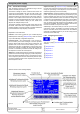
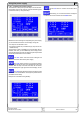
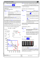
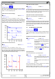
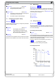
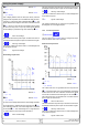
Table Of Contents
- 1. Einleitung
- 2. Technische Daten
- 3. Gerätebeschreibung
- 4. Allgemeines zum Gerät
- 5. Installation
- 6. Bedienung
- 6.1 Die Anzeige
- 6.2 Verwendete Symbolik
- 6.3 Übersicht über die Anzeigeelemente
- 6.4 Einschalten des Ausgangs
- 6.5 Sollwerte einstellen
- 6.6 Schrittweiten bei Sollwerteinstellung
- 6.7 Tastenfeld umschalten
- 6.8 Bedieneinheit sperren
- 6.9 Bedienort wechseln
- 6.10 Umschalten in den Funktionsmanager
- 6.11 Umschalten ins Menü
- 6.12 Parameterseiten
- 6.13 Alarme, Warnungen und Meldungen
- 6.14 Quittieren von Alarmen und Warnungen
- 6.15 Der Funktionsmanager
- 7. Gerätekonfiguration
- 7.1 Betriebsparameter definieren
- 7.2 Voreinstellung von Sollwertsätzen
- 7.3 Einstellgrenzen
- 7.4 Bedieneinheit konfigurieren
- 7.5 Display einstellen
- 7.6 Überwachung
- 7.7 Grundeinstellung wiederherstellen
- 7.8 Aktivierung der Photovoltaik-Funktion
- 7.9 Freischaltung der U/I/R Betriebsart
- 7.10 Sperren der Geräte-Konfiguration
- 8. Verhalten bei ...
- 9. Wechselbare Schnittstellen
- 10. Eingebaute Analogschnittstelle
- 11. PV - Solarmodul-Simulation
- 12. HS - High-Speed-Modifikation
- 13. Sonstiges
- 1. Introduction
- 2. Technical specifications
- 3. Device description
- 4. General
- 5. Installation
- 6. Handling
- 6.1 The display
- 6.2 Used symbols
- 6.3 Short overview about the display elements
- 6.4 Switching the power output on
- 6.5 Adjusting set values
- 6.6 Step widths for set value adjustment
- 6.7 Switching the button panel
- 6.8 Locking the control panel
- 6.9 Changing the location mode
- 6.10 Switching to the function manager
- 6.11 Activating the menu
- 6.12 Parameter pages
- 6.13 Alarms, warnings and signals
- 6.14 Acknowledging alarms and warnings
- 6.15 The function manager
- 7. Device configuration
- 7.1 Defining operation parameters
- 7.2 Predefining preset lists
- 7.3 Adjustment limits
- 7.4 Configuring the control panel
- 7.5 Configuring the graphic display
- 7.6 Supervision
- 7.7 Reset to default configuration
- 7.8 Activating the photovoltaics feature
- 7.9 Unlocking the U/I/R mode
- 7.10 Locking the device configuration
- 8. Behaviour of the device when...
- 9. Pluggable interface cards
- 10. Built-in analogue interface
- 11. PV - Solar panel simulation
- 12. HS - High speed ramping
- 13. Miscellaneous
53
Instruction Manual
PSI 8000 3U HS PV Series
EN
Date: 10-28-2011
Using the power supply
6.15 The function manager
Note: the function manager is not available as long as the PV
feature is enabled (see section 7.8)!
The function manager is used to create functions which can
control the unit automatedly. The user can build curves of set
values after the function f(U, I, ∆t) with it. The function manager
sets the set values in an interval of 2ms. This means, that only
times for ∆t of a multiple of 2ms can be set, for instance 50ms.
If voltage or current changes between two points, a ramp which
consists of a certain number of steps (∆t : 2ms, results in 25
steps for the example above) is built.
The function manager controls the power supply and puts the
set values, which have been congured in the function. The
actual progression of the output values is however determined
by the load and the output capacity of the device.
Explanation of the used terms:
Function = the function consists of up to 5 linked sequence
headers (starts in menu atSetup function), which can consist
of up to ve differently congurable sequences.
Function layout = the configurations in the function lay-
out are used by the function manager to set the operation
(U/I/P or U/I/R) mode for the power supply. Furthermore, the
repetition rate of the function and the arbitrary order of the
sequences are set here. In dependency of the function layout
the function manager processes the next sequence after the
previous one has been processed and uses the settings from
the sequence control of the next sequence.
Sequence = consists of the sequence control and 10 sequence
points. If the function manager is going to process a sequence,
it rst of all sets the parameters given in the sequence control.
The 10 sequence points are set consecutively and the whole
process is repeated as often as the repetition rate for the par-
ticular sequence is set to.
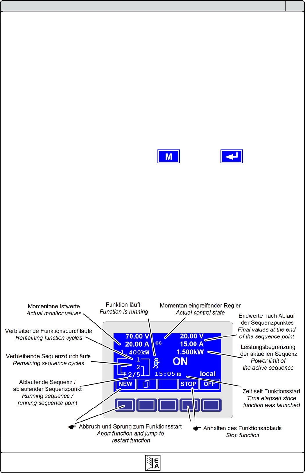
Overview of the function manager display:
Figure 8
Sequence control (Sequence control) = denes the repeti-
tion rate of the sequence and the maximum set value of power
during the processing of the sequence, as well as internal
resistance (optionally, has to be unlocked).
Sequence point = a sequence always consists of 10 sequence
points. The points are processed (=set) consecutively by the
function manager from point 0 to point 9. The denition of the
sequence point determines, which set values for voltage and
current have to be reached after the given time ∆t. This enables
the user to create step functions by setting the time to 0ms or
2ms, as well as ramps with times from 4ms to 99h99m. A time
value of 0ms is settable, but results in a real time value of 2ms,
because set values are only set in 2ms steps.
Additionally to the function itself you can set up and use the
supervision circuits in the proles. The function manager can
also be controlled via the communication with the interface
cards with one additional feature: you can set a stop point at
which the function shall stop.
6.15.1 Conguring the function
+Function +
The menu pageFunction leads to the following menu
selection:
Setup function
Sequence 1
Sequence 2
Sequence 3
Sequence 4
Sequence 5