
User manual

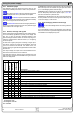
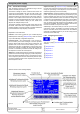
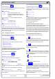
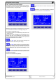
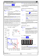
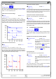
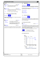
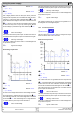
Table Of Contents
- 1. Einleitung
- 2. Technische Daten
- 3. Gerätebeschreibung
- 4. Allgemeines zum Gerät
- 5. Installation
- 6. Bedienung
- 6.1 Die Anzeige
- 6.2 Verwendete Symbolik
- 6.3 Übersicht über die Anzeigeelemente
- 6.4 Einschalten des Ausgangs
- 6.5 Sollwerte einstellen
- 6.6 Schrittweiten bei Sollwerteinstellung
- 6.7 Tastenfeld umschalten
- 6.8 Bedieneinheit sperren
- 6.9 Bedienort wechseln
- 6.10 Umschalten in den Funktionsmanager
- 6.11 Umschalten ins Menü
- 6.12 Parameterseiten
- 6.13 Alarme, Warnungen und Meldungen
- 6.14 Quittieren von Alarmen und Warnungen
- 6.15 Der Funktionsmanager
- 7. Gerätekonfiguration
- 7.1 Betriebsparameter definieren
- 7.2 Voreinstellung von Sollwertsätzen
- 7.3 Einstellgrenzen
- 7.4 Bedieneinheit konfigurieren
- 7.5 Display einstellen
- 7.6 Überwachung
- 7.7 Grundeinstellung wiederherstellen
- 7.8 Aktivierung der Photovoltaik-Funktion
- 7.9 Freischaltung der U/I/R Betriebsart
- 7.10 Sperren der Geräte-Konfiguration
- 8. Verhalten bei ...
- 9. Wechselbare Schnittstellen
- 10. Eingebaute Analogschnittstelle
- 11. PV - Solarmodul-Simulation
- 12. HS - High-Speed-Modifikation
- 13. Sonstiges
- 1. Introduction
- 2. Technical specifications
- 3. Device description
- 4. General
- 5. Installation
- 6. Handling
- 6.1 The display
- 6.2 Used symbols
- 6.3 Short overview about the display elements
- 6.4 Switching the power output on
- 6.5 Adjusting set values
- 6.6 Step widths for set value adjustment
- 6.7 Switching the button panel
- 6.8 Locking the control panel
- 6.9 Changing the location mode
- 6.10 Switching to the function manager
- 6.11 Activating the menu
- 6.12 Parameter pages
- 6.13 Alarms, warnings and signals
- 6.14 Acknowledging alarms and warnings
- 6.15 The function manager
- 7. Device configuration
- 7.1 Defining operation parameters
- 7.2 Predefining preset lists
- 7.3 Adjustment limits
- 7.4 Configuring the control panel
- 7.5 Configuring the graphic display
- 7.6 Supervision
- 7.7 Reset to default configuration
- 7.8 Activating the photovoltaics feature
- 7.9 Unlocking the U/I/R mode
- 7.10 Locking the device configuration
- 8. Behaviour of the device when...
- 9. Pluggable interface cards
- 10. Built-in analogue interface
- 11. PV - Solar panel simulation
- 12. HS - High speed ramping
- 13. Miscellaneous
51
Instruction Manual
PSI 8000 3U HS PV Series
EN
Date: 10-28-2011
Using predened set values
A table of up to 4 sets of set values is accessible in the menu
Preset List (see „7.2. Predening preset lists“). The left knob
selects the preset list and with the RETURN button the set is
submitted or discarded with the ESC button.
The chosen set is still 1. After the RETURN button
is pressed, the set values of set 3 are submitted to the power
supply. The display then shows the new set values of set 3.
The ORY button can be used to jump straight to the
menu page where the preset lists are dened and there they‘re
edited and submitted with RETURN as usual.
6.6 Step widths for set value adjustment
Voltage Current
Nom. val Coarse Fine Nom. val Coarse Fine
600V 5V 0.1V 30A 0.2A 10mA
1000V 10V 1V 70A 0.5A 10mA
1500V 10V 1V
Power Resistance
Nom. val Coarse Fine Nom. val Coarse Fine
10kW 0.10kW 0.01kW 171/667Ω 0.1Ω 1Ω
15kW 0.10kW 0.01kW 1.000kΩ 1Ω 10Ω
Note: The resolution of the set value adjustment in some cases
is, depending on the nominal values, higher than the one of the
output voltage. Thus it can happen that the output voltage only
changes every 2 or 3 steps.
6.7 Switching the button panel
The button PAGE is used to switch to another button
panel. The new button assignments of the other panel allow the
user to lock the control panel, switch to the function manager
or set the location mode.
6.8 Locking the control panel
The button „Lock button panel“ locks all buttons, except
itself, and the rotary knobs. The unit is now locked from manu-
al acess, so that no set value can be changed or no menu is
accessible. The locking mode can be set up in the menu. The
control panel can be either completely inactive or it can exclude
the OFF button (the unit is then locked but can be switched off
and on by the OFF button). See also „Control panel lock“ in
section „7.4. Conguring the control panel“.
After the control panel was locked it changes to this
icon. The button can be used to unlock the control panel again,
if button
is pressed within 2s.
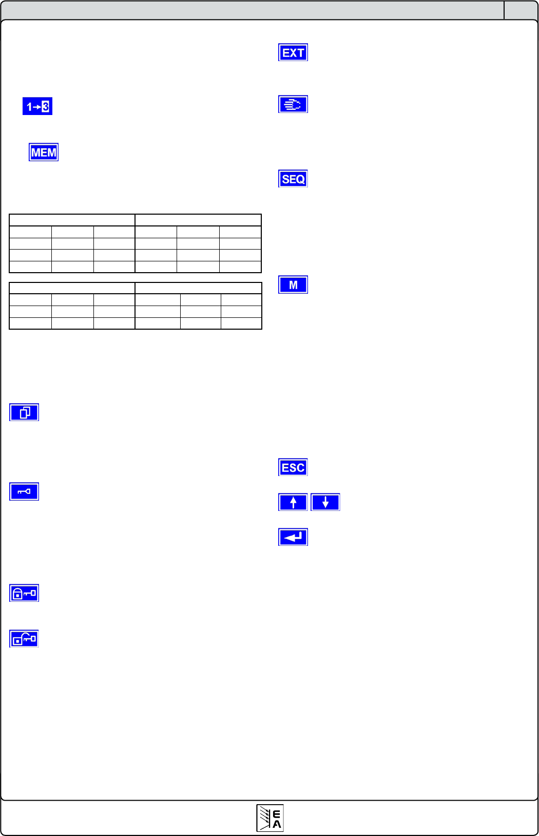
6.9 Changing the location mode
With the button EXT the user enables the remote control
of the unit via a digital or analogue interface card and deactivates
the local mode.
With the hand button the user sets the unit into strict
local mode, so that it is only manually controllable. Access
by any interface, analogue or digital, is then blocked.
6.10 Switching to the function manager
The SEQ button switches the display to the function
manager mode.
Switching to the function manager is only possible while the unit
is in standby (output = off). The set values of voltage and current
are set to 0V and 0A. For details about the function manager
see section „6.15. The function manager“.
6.11 Activating the menu
The main menu is acessed with the MENU button and
the display changes to the main menu level. A text menu like
this appears:
Prole
Setting up and selecting user proles
Function Setting up a function sequence
Analogue interface
Settings for the internal analogue inter-
face
Communication Congure the pluggable interface card
Options Default setup, unlock features, lock
device conguration
About… Ma
nufacturer, service, SW version etc.
A menu page is left to the next higher level by pressing
the ESC button.
The SELECT keys are used to select another
menu entry.
The RETURN button then enters the menu entry into
the next sublevel by pressing it. The lowest menu level always
shows up as a parameter page. See next topic for details.
Using the power supply