
User manual


Table Of Contents
- 1. Einleitung
- 2. Technische Daten
- 3. Gerätebeschreibung
- 4. Allgemeines zum Gerät
- 5. Installation
- 6. Bedienung
- 6.1 Die Anzeige
- 6.2 Verwendete Symbolik
- 6.3 Übersicht über die Anzeigeelemente
- 6.4 Einschalten des Ausgangs
- 6.5 Sollwerte einstellen
- 6.6 Schrittweiten bei Sollwerteinstellung
- 6.7 Tastenfeld umschalten
- 6.8 Bedieneinheit sperren
- 6.9 Bedienort wechseln
- 6.10 Umschalten in den Funktionsmanager
- 6.11 Umschalten ins Menü
- 6.12 Parameterseiten
- 6.13 Alarme, Warnungen und Meldungen
- 6.14 Quittieren von Alarmen und Warnungen
- 6.15 Der Funktionsmanager
- 7. Gerätekonfiguration
- 7.1 Betriebsparameter definieren
- 7.2 Voreinstellung von Sollwertsätzen
- 7.3 Einstellgrenzen
- 7.4 Bedieneinheit konfigurieren
- 7.5 Display einstellen
- 7.6 Überwachung
- 7.7 Grundeinstellung wiederherstellen
- 7.8 Aktivierung der Photovoltaik-Funktion
- 7.9 Freischaltung der U/I/R Betriebsart
- 7.10 Sperren der Geräte-Konfiguration
- 8. Verhalten bei ...
- 9. Wechselbare Schnittstellen
- 10. Eingebaute Analogschnittstelle
- 11. PV - Solarmodul-Simulation
- 12. HS - High-Speed-Modifikation
- 13. Sonstiges
- 1. Introduction
- 2. Technical specifications
- 3. Device description
- 4. General
- 5. Installation
- 6. Handling
- 6.1 The display
- 6.2 Used symbols
- 6.3 Short overview about the display elements
- 6.4 Switching the power output on
- 6.5 Adjusting set values
- 6.6 Step widths for set value adjustment
- 6.7 Switching the button panel
- 6.8 Locking the control panel
- 6.9 Changing the location mode
- 6.10 Switching to the function manager
- 6.11 Activating the menu
- 6.12 Parameter pages
- 6.13 Alarms, warnings and signals
- 6.14 Acknowledging alarms and warnings
- 6.15 The function manager
- 7. Device configuration
- 7.1 Defining operation parameters
- 7.2 Predefining preset lists
- 7.3 Adjustment limits
- 7.4 Configuring the control panel
- 7.5 Configuring the graphic display
- 7.6 Supervision
- 7.7 Reset to default configuration
- 7.8 Activating the photovoltaics feature
- 7.9 Unlocking the U/I/R mode
- 7.10 Locking the device configuration
- 8. Behaviour of the device when...
- 9. Pluggable interface cards
- 10. Built-in analogue interface
- 11. PV - Solar panel simulation
- 12. HS - High speed ramping
- 13. Miscellaneous
70
© 2006, Elektro-Automatik GmbH & Co. KG
Irrtümer und Änderungen vorbehalten
EN
Instruction Manual
PSI 8000 3U HS PV Series
Date: 10-28-2011
Operating the device
12. HS - High speed ramping
The power supply features an integrated HS feature which pro-
vides improved dynamics of the output voltage due to reduced
output capacities.
This is a permanent modication which can not be deactivated
and will effect some of the standard technical specications.
See table on the next page.
Voltage overshoot!
Power supplies with High Speed option can produce
very high voltage overshoots on the output, if the load
changes. The electric strength of connected loads
must be observed!
12.1 Restrictions
• Remote sense operation and series connection are not
available and not allowed!
• The fall time t
Fall
is load depending and can be calculated by
the user from the given output capacity
• In case the given time and power dissipation for permanent
pulsed operation are not adhered, the warranty claim expires
12.2 Terms explained
C
OUT
Remaining output capacity of the modied unit, is used to calcu-
late time values regarding the dynamics of the output voltage.
U
MIN
> / P
MIN
>
Recommended mininum output voltage resp. minimum actual
power the device should be operated with. Below these values
the output ripple is expected to be even higher than stated in
the table above.
Fall time
Together with the rise time, this is an important value regarding
the output voltage dynamics. This value is primarily depending
on the load‘s resistance.
Rise time
Together with the fall time, this is an important value regarding
the output voltage dynamics. This values is depending on the
output capacity, the load‘s resistance and the adjusted current
limit.
12.3 General operation instructions
Permanent remote control which results in a big ∆U/∆t is allo-
wed, as long as a certain total internal power dissipation loss
is not exceeded. It is calculated with the formula dU
max
= √ (F
/ f) (if frequency is given) or f
max
= F / dU² (if voltage difference
is given) and with F = 192000 for permanent pulsed operation,
whereas f is the frequency of the pulsed operation, dU the
voltage difference of the rising or falling edge and F a factor.
Permanent pulsed operation here means for hours or days.
Short-time operation, e.g. some minutes followed by a break of
the same period, allows higher load dynamics with F = 256000.
Recommended mininum output voltage resp. minimum actual
power the device should be operated with. Below these values
the output ripple is expected to be even higher than stated in
the table above.
12.4 Specic instructions for the 1500V model
Extreme pulse-shaped unload, for example 90% I
nom
-> 5% I
nom
,
can produce a voltage rise of up to +100V. Otherwise, a voltage
rise of 40V…60V is typical.
The time of the falling edge is load-dependent. With, for exam-
ple, 1A constant load t
fall
will be ~67V/ms, at no-load condition
it is always 1.7s down to 0V.
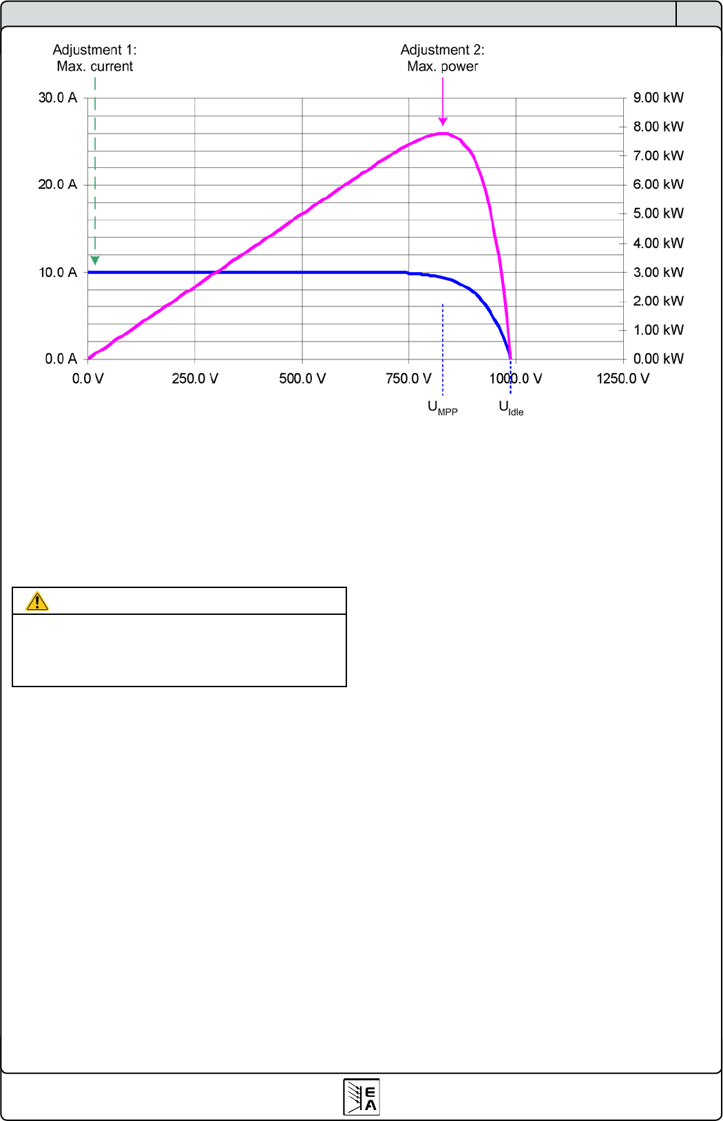
Figure 13. Expected PV curve of the simulation