
User manual


Table Of Contents
- 1. Einleitung
- 2. Technische Daten
- 3. Gerätebeschreibung
- 4. Allgemeines zum Gerät
- 5. Installation
- 6. Bedienung
- 6.1 Die Anzeige
- 6.2 Verwendete Symbolik
- 6.3 Übersicht über die Anzeigeelemente
- 6.4 Einschalten des Ausgangs
- 6.5 Sollwerte einstellen
- 6.6 Schrittweiten bei Sollwerteinstellung
- 6.7 Tastenfeld umschalten
- 6.8 Bedieneinheit sperren
- 6.9 Bedienort wechseln
- 6.10 Umschalten in den Funktionsmanager
- 6.11 Umschalten ins Menü
- 6.12 Parameterseiten
- 6.13 Alarme, Warnungen und Meldungen
- 6.14 Quittieren von Alarmen und Warnungen
- 6.15 Der Funktionsmanager
- 7. Gerätekonfiguration
- 7.1 Betriebsparameter definieren
- 7.2 Voreinstellung von Sollwertsätzen
- 7.3 Einstellgrenzen
- 7.4 Bedieneinheit konfigurieren
- 7.5 Display einstellen
- 7.6 Überwachung
- 7.7 Grundeinstellung wiederherstellen
- 7.8 Aktivierung der Photovoltaik-Funktion
- 7.9 Freischaltung der U/I/R Betriebsart
- 7.10 Sperren der Geräte-Konfiguration
- 8. Verhalten bei ...
- 9. Wechselbare Schnittstellen
- 10. Eingebaute Analogschnittstelle
- 11. PV - Solarmodul-Simulation
- 12. HS - High-Speed-Modifikation
- 13. Sonstiges
- 1. Introduction
- 2. Technical specifications
- 3. Device description
- 4. General
- 5. Installation
- 6. Handling
- 6.1 The display
- 6.2 Used symbols
- 6.3 Short overview about the display elements
- 6.4 Switching the power output on
- 6.5 Adjusting set values
- 6.6 Step widths for set value adjustment
- 6.7 Switching the button panel
- 6.8 Locking the control panel
- 6.9 Changing the location mode
- 6.10 Switching to the function manager
- 6.11 Activating the menu
- 6.12 Parameter pages
- 6.13 Alarms, warnings and signals
- 6.14 Acknowledging alarms and warnings
- 6.15 The function manager
- 7. Device configuration
- 7.1 Defining operation parameters
- 7.2 Predefining preset lists
- 7.3 Adjustment limits
- 7.4 Configuring the control panel
- 7.5 Configuring the graphic display
- 7.6 Supervision
- 7.7 Reset to default configuration
- 7.8 Activating the photovoltaics feature
- 7.9 Unlocking the U/I/R mode
- 7.10 Locking the device configuration
- 8. Behaviour of the device when...
- 9. Pluggable interface cards
- 10. Built-in analogue interface
- 11. PV - Solar panel simulation
- 12. HS - High speed ramping
- 13. Miscellaneous
58
© 2006, Elektro-Automatik GmbH & Co. KG
Irrtümer und Änderungen vorbehalten
EN
Instruction Manual
PSI 8000 3U HS PV Series
Date: 10-28-2011
Using the power supply
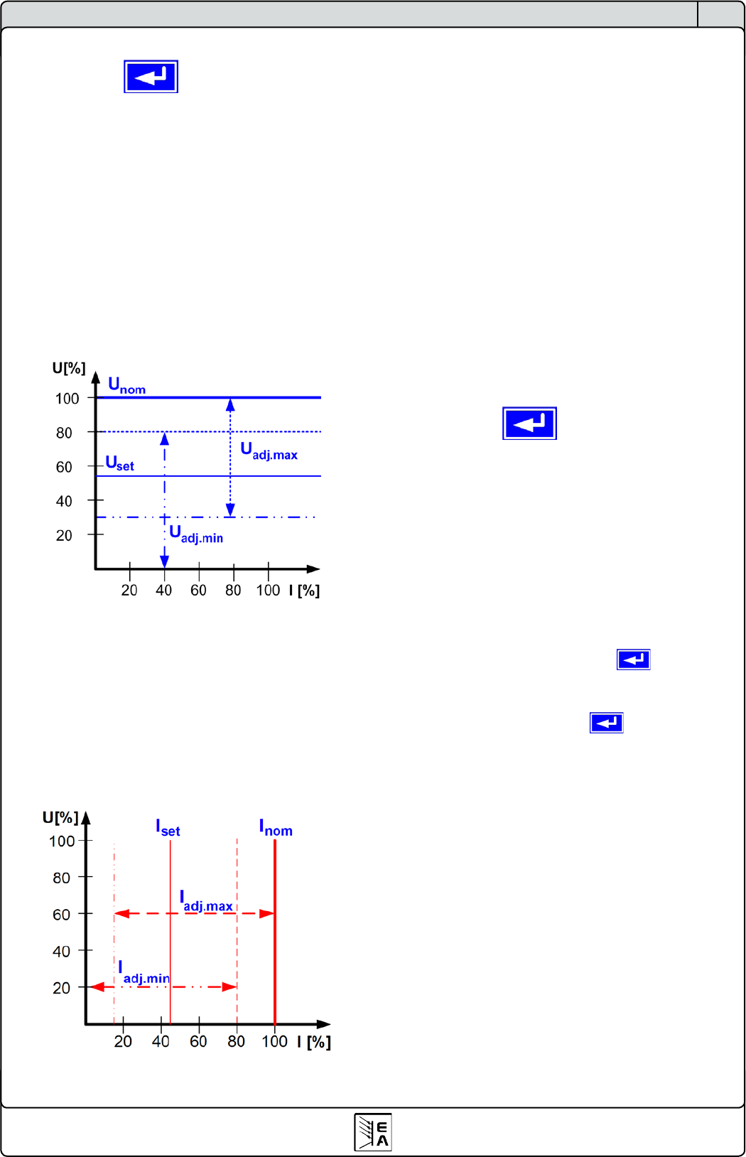
7.3 Adjustment limits
Adjust limits +
The maximum and minimum adjustment limits can be dened
here. These limits are always interfering, in local or remote
mode, i.e. unit is controlled by a PC.
Limits of the set value of voltage
U adj Default: 0V, U
nom
= {U
adj.min
} {U
adj.max
}
Whereas U
adj.min
= {0...U
adj.max
} and U
adj.max
= {U
adj.min
...U
nenn
}
You can dene the lower and upper limit of the adjustable
voltage here. Set values which exceed these limits are not
accepted, neither from the control panel nor from the remote
control via a PC (communication with interface cards).
Limits of the set value of current
I adj Default: 0A, I
nom
= {I
adj.min
} {I
adj.max
}
Whereas I
adj.min
= {0...I
adj.max
} and I
adj.max
= {I
adj.min
...I
nom
}
You can dene the lower and upper limit of the adjustable current
here. Set values which exceed these limits are not accepted,
neither from the control panel nor from the remote control via
a PC (communication with interface cards).
Limit of the set value of power
P adj max Default: P
nom
= {0kW… P
nom
}
You can dene the upper limit of the maximum adjustable power
here. Set values which exceed these limits are not accepted,
neither from the control panel nor from the remote control via
a PC (communication with interface cards).
Limit of the set value of internal resistance
(Optional, only accessible with unlocked U/I/R mode)
R adj max Default: 0Ω
= {0Ω…20 * Ri
nom
}
If the U/I/R mode has been unlocked, you can set the upper limit
of the maximum adjustable internal resistance. Set values which
exceed these limits are not accepted, neither from the control
panel nor from the remote control via a PC (communication
with interface cards).
7.4 Conguring the control panel
Control panel +
The menu page Control panel lets you congure all para-
meters that are related to the graphical display and the control
panel.
Congure how set values are manually adjusted
Accept set value Default: direct
= direct The set values are directly submitted to
the power stage when changed with the
rotary knobs
= return key The changed set values are only set if
submitted with the button.
= from preset list You can choose sets from the
Preset
List
with the rotary knobs and submit
them with the button
Control panel lock
The control panel lock is only congured here.
Key lock Default: except OFF
= except OFF The control panel (buttons and rotary
knobs) will be locked, except for the OFF
button
= enable The rotary knobs and most buttons will
be locked
= disable No lock
The control panel lock is used to prevent from unwanted
changes to the set values or to the settings.
Note: this setting is only temporary. It is reset (=disable) after
the device is switched on again or returns from mains blackout.