
User manual


Table Of Contents
- 1. Einleitung
- 2. Technische Daten
- 3. Gerätebeschreibung
- 4. Allgemeines zum Gerät
- 5. Installation
- 6. Bedienung
- 6.1 Die Anzeige
- 6.2 Verwendete Symbolik
- 6.3 Übersicht über die Anzeigeelemente
- 6.4 Einschalten des Ausgangs
- 6.5 Sollwerte einstellen
- 6.6 Schrittweiten bei Sollwerteinstellung
- 6.7 Tastenfeld umschalten
- 6.8 Bedieneinheit sperren
- 6.9 Bedienort wechseln
- 6.10 Umschalten in den Funktionsmanager
- 6.11 Umschalten ins Menü
- 6.12 Parameterseiten
- 6.13 Alarme, Warnungen und Meldungen
- 6.14 Quittieren von Alarmen und Warnungen
- 6.15 Der Funktionsmanager
- 7. Gerätekonfiguration
- 7.1 Betriebsparameter definieren
- 7.2 Voreinstellung von Sollwertsätzen
- 7.3 Einstellgrenzen
- 7.4 Bedieneinheit konfigurieren
- 7.5 Display einstellen
- 7.6 Überwachung
- 7.7 Grundeinstellung wiederherstellen
- 7.8 Aktivierung der Photovoltaik-Funktion
- 7.9 Freischaltung der U/I/R Betriebsart
- 7.10 Sperren der Geräte-Konfiguration
- 8. Verhalten bei ...
- 9. Wechselbare Schnittstellen
- 10. Eingebaute Analogschnittstelle
- 11. PV - Solarmodul-Simulation
- 12. HS - High-Speed-Modifikation
- 13. Sonstiges
- 1. Introduction
- 2. Technical specifications
- 3. Device description
- 4. General
- 5. Installation
- 6. Handling
- 6.1 The display
- 6.2 Used symbols
- 6.3 Short overview about the display elements
- 6.4 Switching the power output on
- 6.5 Adjusting set values
- 6.6 Step widths for set value adjustment
- 6.7 Switching the button panel
- 6.8 Locking the control panel
- 6.9 Changing the location mode
- 6.10 Switching to the function manager
- 6.11 Activating the menu
- 6.12 Parameter pages
- 6.13 Alarms, warnings and signals
- 6.14 Acknowledging alarms and warnings
- 6.15 The function manager
- 7. Device configuration
- 7.1 Defining operation parameters
- 7.2 Predefining preset lists
- 7.3 Adjustment limits
- 7.4 Configuring the control panel
- 7.5 Configuring the graphic display
- 7.6 Supervision
- 7.7 Reset to default configuration
- 7.8 Activating the photovoltaics feature
- 7.9 Unlocking the U/I/R mode
- 7.10 Locking the device configuration
- 8. Behaviour of the device when...
- 9. Pluggable interface cards
- 10. Built-in analogue interface
- 11. PV - Solar panel simulation
- 12. HS - High speed ramping
- 13. Miscellaneous
43
Instruction Manual
PSI 8000 3U HS PV Series
EN
Date: 10-28-2011
About the device
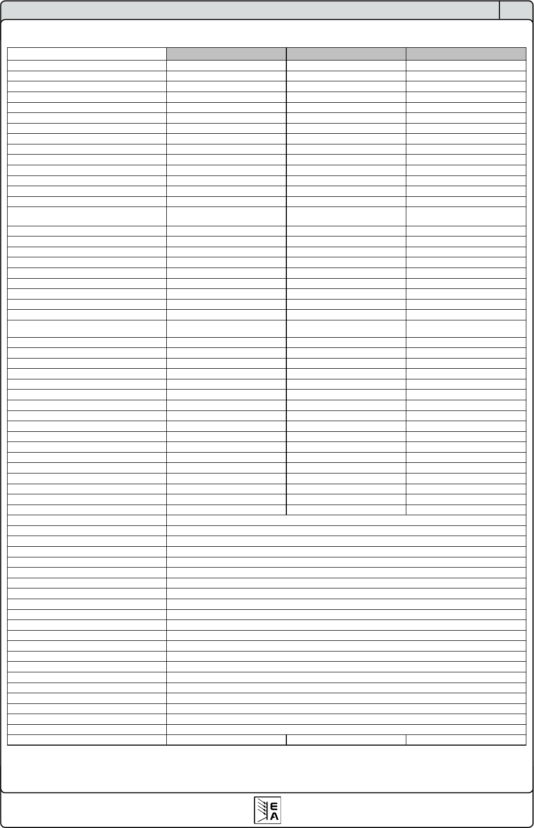
2.2 Device specications
* Related to the nominal value, the accuracy denes the maximum allowed deviation between set value and actual value.
Example: a 80V model has min. 0.2% voltage accuracy. This is 160mV. When setting a voltage of 5V and with an allowed maximum deviation of 160mV, the resulting
actual value could be between 4.84V and 5.16V.
** Enclosure dimensions only, not overall dimensions
PSI 8600-70 3U HS PV PSI 81000-30 3U HS PV PSI 81500-30 3U HS PV
Mains input
Input voltage range 340…460V 340…460V 340…460V
Input voltage range optional 588…796V+MP - 588…796V+MP
Required phases L1, L2, L3, PE L1, L2, L3, PE L1, L2, L3, PE
Input frequency 50/60Hz 50/60Hz 50/60Hz
Input fuse 6x T16A 4x T16A 6x T16A
Input current max. 28A max. 28A max. 28A
Power factor > 0.99 > 0.99 > 0.99
Output - Voltage
Nominal voltage U
Nom
600V 1000V 1500V
Adjustable range
0V…U
Nom
0V…U
Nom
0V…U
Nom
Stability at mains fluctuation ±10% ∆U
IN
< 0.02% < 0.02% < 0.02%
Stability at 0…100% load < 0.05% < 0.05% < 0.05%
Ramp-up time 10...90% at 100% load max. 30ms max. 30ms max. 30ms
Ripple @ BWL 20MHz
< 400mVpp
< 80mVrms
< 800mVpp
< 200mVrms
< 1000mVpp
< 350mVrms
Accuracy* ≤ 0.2% ≤ 0.2% ≤ 0.2%
Resolution of display 100mV 1V 1V
Remote sense compensation max. 18V max. 20V max. 30V
Overvoltage protection threshold (adjustable) 0…660V 0…1100V 0…1650V
Output - Current
Nominal current I
Nom
70A 30A 30A
Adjustable range
0…I
Nom
0…I
Nom
0…I
Nom
Stability at mains fluctuation ±10% ∆U
IN
< 0.05% < 0.05% < 0.05%
Stability at 0…100% ∆U
OUT
< 0.15% < 0.15% < 0.15%
Ripple @ BWL 20MHz
< 30mApp
< 12mArms
< 22mApp
< 11mArms
< 19mApp
< 13mArms
Accuracy* ≤ 0.2% ≤ 0.2% ≤ 0.2%
Resolution of display 10mA 10mA 10mA
Transient recovery time 10….90% load < 2ms < 2ms < 2ms
Output - Power
Nominal power P
Nom
15000W 10000W 15000W
Nominal power at derating
0...P
Nom
0...P
Nom
0...P
Nom
Accuracy* ≤ 0.2% ≤ 0.2% ≤ 0.2%
Resolution of display 0.01kW 0.01kW 0.01kW
Efficiency 95.20% 95.50% 95.50%
Miscellaneous
Ambient temperature 0….50°C 0….50°C 0….50°C
Storage temperature -20….70°C -20….70°C -20….70°C
Humidity rel. < 80% < 80% < 80%
Dimensions (WxHxD) ** 19" 3U 595mm 19" 3U 595mm 19" 3U 595mm
Weight 33kg 25.5kg 33kg
Redundancy no no no
Isolation +output to enclosure 1000V DC 1500V DC 2000V DC
Isolation -output to enclosure
Isolation input to output
Cooling
Safety
EMC standards
Overvoltage class
Protection class
Pollution degree
Operational altitude
Series operation
max. series connection voltage
Master-Slave
Parallel operation
max. parallel connection voltage
Master-Slave
Analogue programming
Isolation voltage
Input range
Accuracy
Input impedance
Digital programming
Article number 09901444 09901438 09901439
Built-in interface: 1500V / Interface card: 2000V
53kOhm
≤ 0.2%
0…5V or 0…10V, selectable
4200V DC
<2000m
1
2
by fans, air inlet on the front, air exhaust on the rear
EN 60950
EN 61326, EN 55022 Class B
2
300V DC
Via pluggable interface cards: RS232, USB, CAN, GPIB, Ethernet
no
600V
1500V
Via built-in isolated analogue interface or pluggable analogue interface card
yes, via Share bus