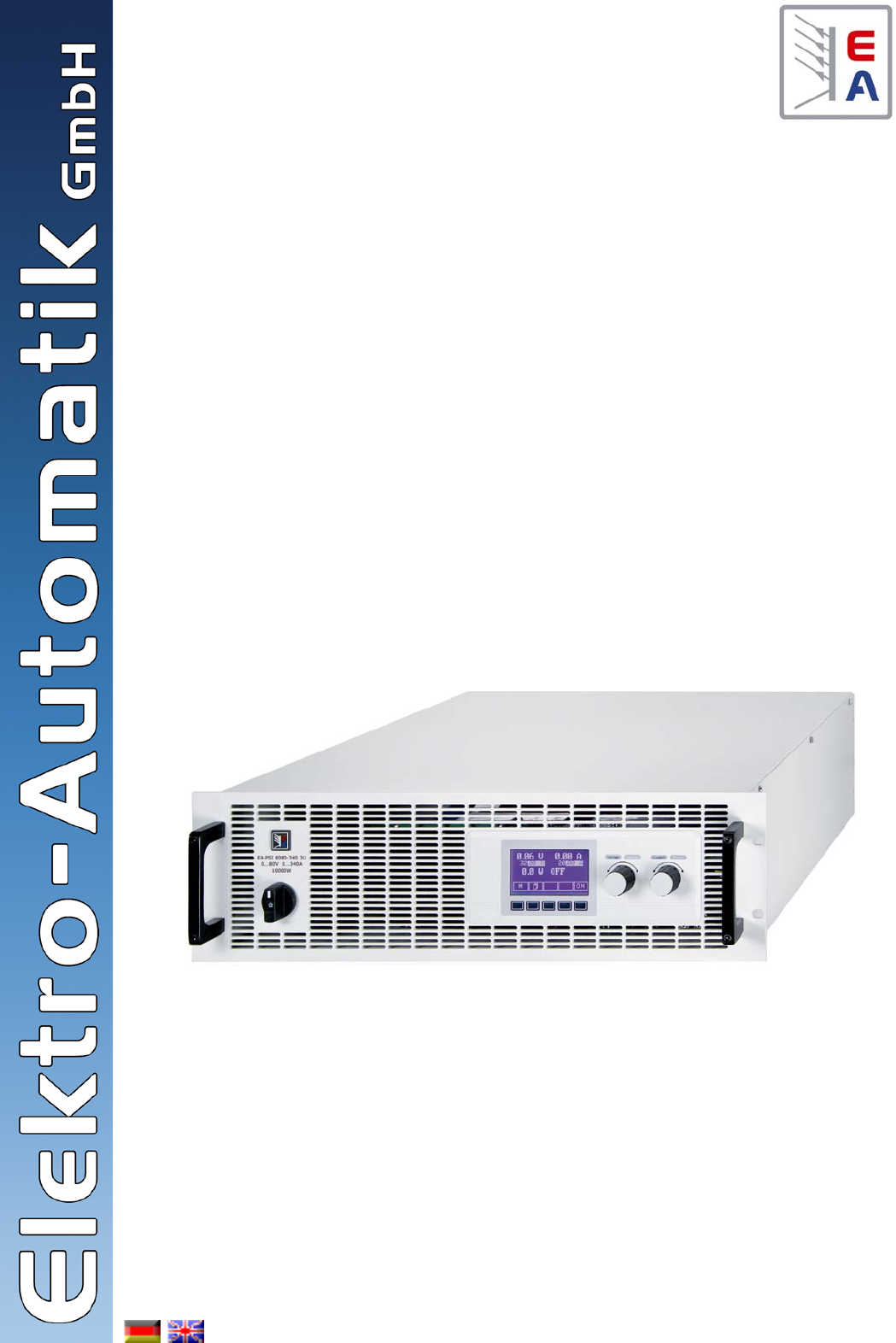
Hochleistungs-Netzgeräteserie High Efficiency Power Supply Series PSI 8000 3U HS PV High Speed Photovoltaics 10kW / 15kW 600V / 1000V / 1500V 30A / 70A PSI 8600-70 3U HS PV: PSI 81000-30 3U HS PV: PSI 81500-30 3U HS PV: 09 901 444 09 901 438 09 901 439
DE Allgemeines Impressum Elektro-Automatik GmbH & Co. KG Helmholtzstrasse 31-33 41747 Viersen Germany Telefon: 02162 / 37850 Fax: 02162 / 16230 Web: www.elektroautomatik.de Mail: ea1974@elektroautomatik.de © Elektro-Automatik Nachdruck, Vervielfältigung oder auszugsweise, zweckentfremdete Verwendung dieser Bedienungsanleitung sind verboten und können bei Nichtbeachtung rechtliche Schritte nach sich ziehen.
Inhaltsverzeichnis DE Seite 1. Einleitung....................................................................................................................................................................................6 2. Technische Daten.......................................................................................................................................................................6 2.1 Bedien- und Anzeigeeinheit.....................................................................
DE Inhaltsverzeichnis Seite 8. Verhalten bei ...........................................................................................................................................................................27 8.1 Einschalten mit dem Netzschalter....................................................................................................................................27 8.2 Ausschalten mit dem Netzschalter....................................................................................
DE Über das Gerät 1. Einleitung Die Hochleistungsnetzgeräte der Serie PSI 8000 3U HS PV sind durch ihr 19“-Einschubgehäuse besonders für Prüfsysteme und Industriesteuerungen geeignet. Über die gängigen Funktionen von Netzgeräten hinaus können Sollwertvorgabesätze eingestellt, gespeichert und bei Bedarf abgerufen werden. Soll- und Istwerte können auf einstellbare Ober- und Untergrenzen hin überwacht, Spannungs- und Stromverläufe mittels eines Funktionsmanagers erzeugt und abgefahren werden.
DE Über das Gerät 2.2 Gerätespezifische Daten PSI 8600-70 3U HS PV PSI 81000-30 3U HS PV PSI 81500-30 3U HS PV Netzeingang Eingangsspannungsbereich Eingangsspannungsbereich opt. 340…460V 340…460V 340…460V 588…796V+MP - 588…796V+MP Benötigte Phasen L1, L2, L3, PE L1, L2, L3, PE L1, L2, L3, PE Eingangsfrequenz 50/60Hz 50/60Hz 50/60Hz Eingangssicherung 6x T16A 4x T16A 6x T16A Eingangsstrom max. 28A max. 28A max. 28A Leistungsfaktor > 0.99 > 0.99 > 0.
DE Über das Gerät E - DC-Ausgang F - Netzanschluß B - Bedienteil C - Schnittstellenkarteneinschub Ansichten D - Sharebus- und Fernfühlungsanschlüsse 3.1 Gerätebeschreibung A - Netzzschalter 3. 8 Stand: 28.10.2011 Bild 2 Bild 1 © 2006, Elektro-Automatik GmbH & Co.
DE Bedienungsanleitung PSI 8000 3U HS PV Serie Bild 4 Bild 3 Über das Gerät Stand: 28.10.
DE Über das Gerät © 2006, Elektro-Automatik GmbH & Co. KG Irrtümer und Änderungen vorbehalten Bild 5 10 Stand: 28.10.
DE Über das Gerät 3.2 Lieferumfang Hier wird vom Anschluß eines einzelnen Gerätes ausgegangen: 1 x Netzgerät L1 1 x Gedruckte Bedienungsanleitung(en) mit CD 1 x Stecker für Sharebus (am Gerät) 1 x Stecker für Fernfühlung (am Gerät) L2 L3 ø Imax ø Imax ø Imax 10kW 4mm² 28A 4mm² 16A 4mm² 16A 15kW 4mm² 28A 4mm² 28A 4mm² 28A 4. Allgemeines zum Gerät Es ergibt sich aus der Tabelle heraus die Empfehlung 4.
DE Über das Gerät 5.7 Anschlußklemme Fernfühlung (Sense) Soll der Spannungsabfall auf den Zuleitungen vom Netzgerät zum Verbraucher hin kompensiert werden, kann das Netzgerät die Spannung am Verbraucher erfassen und daraufhin ausregeln. Für die maximale Höhe der Ausregelung siehe Abschnitt „2.2. Gerätespezifische Daten“, Angabe „Senseausregelung“. Der Anschluß für die Fernfühlung befindet auf der Rückseite, Klemme „Sense“. Siehe auch Abschnitt 3.1.
DE Über das Gerät 6. Bedienung 6.1 Die Anzeige Bild 7 zeigt eine Übersicht über die Aufteilung der grafischen Anzeige. Das Display stellt im Normalbetrieb die Ist- und Sollwerte für Spannung (oben links), Strom (oben rechts) und Leistung (unten links), sowie Parameter und Einstellungen in der ���������������������������������������������������������� Gerätekonfiguration��������������������������������������� .
DE Über das Gerät Der Zustand des Leistungsausganges wird im rechten unteren Displaybereich angezeigt. {ON,OFF} Zustand des Leistungsausganges Der Status des momentan eingreifenden Reglers wird rechts neben dem zugehörigen Istwert angezeigt. Die Ausgangswerte des Netzgerätes werden begrenzt: - durch den Spannungssollwert (= Constant Voltage) 6.5 Sollwerte einstellen Solange im Display der Status extern oder remote nicht angezeigt wird, können Sollwerte manuell eingestellt werden.
DE Über das Gerät Im Menü Preset List (siehe „7.2. Voreinstellung von Sollwertsätzen“) ist eine Tabelle mit bis zu 4 frei definierbaren Sollwertsätzen hinterlegt. Mit dem linken Drehknopf wird auf den nächsten Sollwertsatz umgeschaltet. Die Sollwerte werden mit der RETURN-Bedientaste übernommen oder mit der ESCBedientaste wieder verworfen. 6.9 Bedienort wechseln Der Benutzer kann über die Bedientaste EXT den Zugriff einer digitalen oder analogen Schnittstelle freigeben.
DE Über das Gerät 6.12 Parameterseiten Die Parameterseite ist die unterste Einstellebene. Hier können Parameter überprüft und verändert werden. Nach Drücken der ESC-Taste wird die Parameterseite in die nächsthöhere Ebene verlassen. Es werden keine Parameter übernommen, auch nicht die, die in der aktuellen Parameterseite eingestellt wurden. Über die Auswahl-Tasten können Sie den gewünschten Parameter in der Anzeige auswählen, er wird daraufhin invertiert dargestellt.
DE Bedienung des Gerätes 6.15 Der Funktionsmanager Hinweis: der Funktionsmanager ist bei aktivierter PV-Option (siehe auch Abschnitt 7.8) nicht verfügbar! Der Funktionsmanager dient zur Erstellung von Funktionsabläufen, die zur automatisierten Ansteuerung des Gerätes verwendet werden können. Über ihn können Sollkurven nach einer Funktion f(U, I, ∆t) erzeugt werden. Er stellt die Sollwerte in einem Intervall von 2ms. Somit können nur Zeiten für ∆t erzeugt werden, die ein Vielfaches von 2ms betragen, z.B.
DE Bedienung des Gerätes 6.15.2 Der Funktionsaufbau Nur mit Option „Innenwiderstand“ (freischaltbar): R seq= {0Ω...20 * Ri Setup function + Nenn Man kann hier die Betriebsart des Netzgerätes und die Wiederholrate der Funktion festlegen. = U/I/R Grundeinstellung: RNenn Während des Ablaufs der Sequenz gilt der eingestellte Innenwiderstand. 6.15.
DE Bedienung des Gerätes 15:05 m Beispiel für Simulation im OFF-Zustand: Es wird die abgearbeitete Zeit seit dem Start des Funktionsablaufs angezeigt. Nach einem Stopp wird die Zeit angehalten. Über die STEP , RUN oder GO Taste wird der Funktionsablauf fortgeführt. Die Zeit läuft danach weiter. {ON,OFF} Zustand des Ausgangs Neben dem Zustand des Ausgangs kann ein Alarm, Warnung oder Meldung erscheinen. 6.15.
DE Bedienung des Gerätes 7. Gerätekonfiguration Teil 1: Das Menü Profile Hier eine Übersicht über die Menüauswahl- und Parameterseiten. Farbig dargestellte Elemente erscheinen nicht bei jedem Modell oder sind ggf. optional. +Profile + Die Profile sollen zeitaufwendige Einstellungen bei wechselnden Benutzern oder Anwendungen erleichtern bzw. gleichbleibende Einstellungen bei sich wiederholenden Anwendungen gewährleisten.
DE Bedienung des Gerätes 7.1 Betriebsparameter definieren Setup operation mode + Die Art der Sollwerteinstellung, die Betriebsart des Gerätes, die Reaktion beim Wiedereinschalten und das Verhalten nach einer Übertemperatur können Sie hier festlegen. CR Im Display wird während des U/I/R-Betriebs der Eingriff des Innenwiderstandsreglers angezeigt. Der Innenwiderstand Risoll wird in der Betriebsanzeige anstatt des eingestellten Leistung Psoll angezeigt.
DE Bedienung des Gerätes 7.3 Einstellgrenzen Einstellgrenze des Leistungssollwertes P adj max Adjust limits + Grundeinstellung: Pnenn = { 0 kW… Pnenn } Die maximalen und minimalen Einstellgrenzen können hier festgelegt werden. Sie gelten sowohl im lokalen Betrieb als auch im externen Betrieb über die Schnittstellenkarten. Man kann hier die maximale Einstellgrenze der Leistung einstellen.
DE Bedienung des Gerätes 7.
DE Bedienung des Gerätes U> Grundeinstellung: UNenn Tu> Grundeinstellung: 100ms = { U<… Uovp} = { 0…99:59h} Diese Art der Spannungsüberwachung unterscheidet sich vom OVP (siehe oben) dadurch, daß der Anwender festlegen kann, ob nur Meldung oder Abschaltung des Ausgangs nach einer einstellbaren Ansprechzeit Tu> erfolgt, wenn die eingestellte Schwelle erreicht wurde.
DE Bedienung des Gerätes 7.6.3 Überstrom überwachen Sollwertsprünge überwachen Step response + Über die Parameterseite Step response werden die Überwachungskreise für den dynamischen und statischen Vergleich des Sollwertes mit dem Istwert eingestellt.
DE Bedienung des Gerätes 7.8 Meldungen des Soll-/ Istvergleichs Beispiel: Der Sprung von einem kleineren Sollwert auf einen größeren Sollwert wurde nicht innerhalb der eingestellten Einschwingzeit Tsr ausgeführt. Die Auslösung wird gemeldet als Alarm, Warnung oder einfache Meldung. U oder U oder U Abhängig von Step response wird alternativ eine I Meldung angezeigt.
DE Bedienung des Gerätes 8. Verhalten bei ... 8.1 Einschalten mit dem Netzschalter Der Netzschalter befindet sich auf der Vorderseite. Nach dem Einschalten zeigt das Gerät in der Anzeige das Herstellerlogo, den Herstellernamen, sowie den Gerätetyp und einen eventuellen Benutzertext an und ist danach betriebsbereit. Im Setup (siehe Abschnitt „7. Gerätekonfiguration“) befindet sich eine Option „Power On“, die bestimmt wie der Zustand des Gerätes nach dem Einschalten ist.
DE Bedienung des Gerätes Der sich durch den Lastwiderstand ergebende Strom ergibt zusammen mit der Ausgangsspannung die gewünschte Ausgangsleistung. Da sich Strom-, Spannungs- und Leistungsregelung gegenseitig beeinflussen, ergäben sich z. B. folgende Verhaltensweisen: Beispiel 1: Gerät ist im Spannungsregelbetrieb, dann wird durch den Anwender die Leistung begrenzt. Als Folge sinkt die Ausgangsspannung und als Folge davon sinkt der Ausgangsstrom.
DE Bedienung des Gerätes 9. Wechselbare Schnittstellen 10. Eingebaute Analogschnittstelle 9.1 Allgemeines 10.1 Das Netzgerät unterstützt verschiedene, optional erhältiche Schnittstellenkarten. Alle sind galvanisch getrennt. Folgende Isolationsspannungen sind gegeben: • USB (IF-U1), CAN (IF-C1), RS232 (IF-R1): 2000V DC • GPIB (IF-G1): 2000V DC Die fest eingebaute, galvanisch getrennte (Isolationspannung siehe „2.
DE Bedienung des Gerätes Achtung! Niemals irgendeine Masse der analogen Schnittstelle mit dem DC-Ausgang (Plus oder Minus) des Gerätes verbinden! Das hebt die galvanische Trennung auf und legt das Potential des DC-Ausgangs, das bei Betrieb an trafolosen Wechselrichtern Netzpotential haben kann, auf die analoge Schnittstelle und somit auf die steuernde Applikation, wie z. B. eine SPS. 10.
DE Bedienung des Gerätes 10.4 Pinspezifikation Pin Name 1 VSEL 2 CSEL 3 N.C. 4 DGND Typ* AI AI Bezeichnung Pegel Elektrische Eigenschaften Sollwert Spannung 0…10V bzw. 0...5 V entsprechen 0..100% von UNenn Genauigkeit < 0,2% Sollwert Strom 0…10V bzw. 0...5 V entsprechen 0..
DE Bedienung des Gerätes Zustand LOW kann durch einen niederohmigen Kontakt wie z. B. einen Schalter, Open-Collector-Transistor oder ein Relais hergestellt werden. 10.5.3 Fernsteuerung aktivieren Umschaltung auf Fernsteuerung über die analoge Schnittstelle ist erforderlich, sobald das Gerät nicht nur überwacht (Monitoring), sondern auch mit Sollwerten von außen gesteuert werden soll.
DE 11. PV - Solarmodul-Simulation Die fest integrierte Photovoltaik-Funktionalität ermöglicht dem Gerät, das Verhalten eines Solarmoduls zu simulieren. Dies wird durch eine Kombination von spezieller Hardware und Software realisiert. Die Funktion kann im Setup-Menü des Gerätes aktiviert oder deaktiviert werden, wie beschrieben in „7.8. Aktivierung der Photovoltaik-Funktion“. Solange sie nicht aktiviert ist, verhält sich das Gerät wie ein normales Netzgerät.
DE Bedienung des Gerätes Bild 13. Zu erwartende PV-Kurve der Simulation 12. HS - High-Speed-Modifikation Abfallzeit Die Netzgeräte verfügen über die integrierte HS-Modifikation, die durch reduzierte Ausgangskapazitäten eine deutliche verbesserte Dynamik der Ausgangsspannung erreicht. Zusammen mit der Anstiegszeit ein sehr wichtiger Wert bezüglich der Dynamik der Ausgangsspannung. Sie ist hauptsächlich vom Widerstand der angeschlossenen Last abhängig.
DE Bedienung des Gerätes 12.5 Abweichende technische Daten Modell 600V / 70A 1000V / 30A 1500V / 30A Ausgangskapazität COut noch nicht verfügbar 22.
DE Bedienung des Gerätes Bild 15. Parallelschaltung im Sharebus-Betrieb 13.4 Vernetzung Die Grafiken unten zeigen Beispiele für die digitale Fernsteuerung von mehreren Netzgeräten gleichzeitig in sternförmiger (USB, RS232, Ethernet) oder busförmiger (CAN, GPIB, Profibus) Vernetzung. Es gelten jeweils die für die Schnittstellen und Bussysteme vorhandenen Vorgaben und Beschränkungen.
DE Bedienung des Gerätes 13.5 Ersatzableitstrommessung nach DIN VDE 0701 Eine Firmwareaktualisierung sollte nur vorgenommen werden, wenn nachweislich Fehler in einer bestimmten Version der Firmware bestehen, die durch eine neuere Version behoben werden, oder wenn neue Funktionen integriert wurden. Dies ist nach geltender Norm zulässig.
EN General About Elektro-Automatik GmbH & Co. KG Helmholtzstrasse 31-33 41747 Viersen Germany Phone: +49 2162 / 37850 Fax: +49 2162 / 16230 Web: www.elektroautomatik.de Mail: ea1974@elektroautomatik.de © Elektro-Automatik Reprint, duplication or partly, wrong use of this user instruction manual are prohibited and might be followed by legal consequences.
Table of contents EN Page 1. Introduction...............................................................................................................................................................................42 2. Technical specifications............................................................................................................................................................42 2.1 Control panel and display............................................................................
EN Table of contents Page 8. Behaviour of the device when..................................................................................................................................................63 8.1 Switching on by power switch..........................................................................................................................................63 8.2 Switching off by power switch..................................................................................................
EN About the device 1. Introduction The high efficiency power supplies of the series PSI 8000 3U are ideally suited for test systems and industrial control facilities by their 19“ draw-out case. 2. Technical specifications 2.
EN About the device 2.2 Device specifications PSI 8600-70 3U HS PV PSI 81000-30 3U HS PV PSI 81500-30 3U HS PV Mains input Input voltage range Input voltage range optional Required phases 340…460V 340…460V 340…460V 588…796V+MP - 588…796V+MP L1, L2, L3, PE L1, L2, L3, PE L1, L2, L3, PE Input frequency 50/60Hz 50/60Hz 50/60Hz Input fuse 6x T16A 4x T16A 6x T16A Input current max. 28A max. 28A max. 28A Power factor > 0.99 > 0.99 > 0.
EN About the device E - DC output F - AC input B - Control panel C - Interface card slot Views D - Share bus and remote sense terminals 3.1 Device description A - Mains switch 3. 44 Date: 10-28-2011 Figure 2 Figure 1 © 2006, Elektro-Automatik GmbH & Co.
EN Instruction Manual PSI 8000 3U HS PV Series Figure 4 Figure 3 About the device Date: 10-28-2011 45
EN About the device © 2006, Elektro-Automatik GmbH & Co.
EN About the device 3.2 Scope of delivery L1 1 x Power supply unit 1 x Printed user manual(s) with CD L2 L3 ø Imax ø Imax ø Imax 1 x Plug for Share bus (plugged) 10kW 4mm² 28A 4mm² 16A 4mm² 16A 1 x Plug for remote sense (plugged) 15kW 4mm² 28A 4mm² 28A 4mm² 28A 4. General We recommend to use 4.1 Prologue / Warning for every phase and ground (PE). This instruction manual and the device are intended to be used by users who know about the principle of a power supply.
EN About the device 5.7 Terminal „Sense“ (Remote sense) In order to compensate the voltage drop along the load cables, the power supply can „sense“ the voltage at the load instead at the output. It will regulate the output voltage so that the desired voltage is provided to the load. For maximum regulation see section „2.2. Device specifications“, information „Remote sense compensation“. The connection for remote sense is done at the terminal „Sense“ on the rear side. Also see section 3.1.
EN About the power supply 6. Handling 6.1 The display Figure 8 below shows an overview of the graphical display. During normal operation, the display shows the actual and set values of voltage (upper left), current (upper right) and power (lower left). In device setup mode, it display parameters and settings. In case the optional „internal resistance control“ is unlocked, the power set value might be replaced by the internal resistance set value, depending on what is selected in the device setup. 6.
EN About the power supply The state of the power output is displayed in the bottom right corner of the display. {ON,OFF} State of the power output The presently active control mode is displayed to the right of the related actual values.
EN Using the power supply 6.9 Using predefined set values A table of up to 4 sets of set values is accessible in the menu Preset List (see „7.2. Predefining preset lists“). The left knob selects the preset list and with the RETURN button the set is submitted or discarded with the ESC button. The chosen set is still 1. After the RETURN button is pressed, the set values of set 3 are submitted to the power supply. The display then shows the new set values of set 3.
EN Using the power supply 6.12 Parameter pages The parameter page is the lowest menu level. Here you can change many different parameters in order to set up the device. By pressing the ESC button the parameter page is left to the next higher level and no parameters are accepted. The SELECT keys are used to select a different parameter. The selected parameter is then displayed invertedly and can be changed with the left rotary knob.
EN Using the power supply 6.15 The function manager Note: the function manager is not available as long as the PV feature is enabled (see section 7.8)! The function manager is used to create functions which can control the unit automatedly. The user can build curves of set values after the function f(U, I, ∆t) with it. The function manager sets the set values in an interval of 2ms. This means, that only times for ∆t of a multiple of 2ms can be set, for instance 50ms.
EN Using the power supply 6.15.2 The function layout 6.15.5 Defining the sequence points Setup function + Sequence points 0-4 {5-9} + You can define the operation mode of the power supply and the repetition rate of the function here. A sequence consists of 10 sequence points. A sequence point consists of three values: the set values for U and I together with the time ∆t.
EN Using the power supply 6.15.7 Controlling the function manager The interactive control panel provides keys to control the function manager. You can halt, continue, reset it to the starting point or exit the function by using these keys. Use the GO button to continue the function after it was stopped. Alternatively, you can reset the function manager to the start of the current function with the NEW button.
EN Using the power supply 7. Device configuration Part 1: The menu Profile This is an overview of the parameter pages. Colored menus or parameters may not appear with every model and can be related to options.. +Profile + The profiles are intended to minimize to time needed to set up the device at alternating users or to keep user defined settings for repeating applications. The last used profile is always loaded after the unit is switched on.
EN Using the power supply 7.1 Defining operation parameters CR Setup operation mode + The way of adjusting the set values, which operation mode is used, how the unit shall react after the mains has restored or the behaviour of the unit after an overtemperature error can be configured here. U/I/P or U/I/R operation mode Setup op.
EN Using the power supply 7.3 Adjustment limits Limit of the set value of power P adj max Adjust limits + The maximum and minimum adjustment limits can be defined here. These limits are always interfering, in local or remote mode, i.e. unit is controlled by a PC. Default: Pnom = {0kW… Pnom} You can define the upper limit of the maximum adjustable power here.
EN Using the power supply 7.6 Sounds Key sound = YES = NO Default: NO A short beep signalises a button press No signal if keys are pressed Alarm sound Default: YES Supervision Supervision + The Supervision menu lets you configure the supervision of output voltage, output current and output power. You can also supervise a step function.
EN Using the power supply U> Default: UNom = { U<… Uovp} Tu> Default: 100ms = { 0…99:59h} This is slightly different from the OVP (see above). Here the voltage is also supervised, but it is notified with either an alarm, a warning or a signal and after a definable delay Tu>. The signal vanishes if the voltage is under the thre-shold for the time Tu>. Hence you can supervise overvoltages without getting This error shuts down the power output.
EN Using the power supply Overcurrent supervision 7.6.3 Step response supervision Step response + The menu page Step response lets you configure the supervision circuits for the dynamic and static comparison of actual value and set value.
EN Using the power supply Notifications of the set/actual comparison 7.8 Activating the photovoltaics feature Example: The step from a lower set value to a higher set value was not performed within the settling time Tsr. The supervision error is then notified as alarm, warning or signal. Enable PV mode + With setting enabled, the hardware and software functionality of the photovoltaics feature is enabled. This setting is permanent until altered.
EN Using the power supply 8. Behaviour of the device when... 8.1 Switching on by power switch The power switch is located at the front. After switching on, the device will show some information in the display: manufacturer‘s name, address and logo, device type and firmware version. In the device setup (see section „7. Device configuration“) there is an option „Power On“ that determines the output condition after the device is switched on. Default is „OFF“.
EN Operating the device The product of both values, the actual power, would sink below the previously set power limit and the device would change from constant power regulation (CP) to constant current regulation (CC). Those three conditions CC, CV and CP are also indicated on the appropriate pins of the optional, analogue interface cards or can be read out as status bits via an optional, digital interface card. 8.
EN Operating the device 9. Pluggable interface cards 10. Built-in analogue interface 9.1 General 10.1 General The power supply supports various optionally available interface cards for digital or analogue remote control. All cards are galvanically isolated. Following isolation voltages are given: The integrated, galvanically isolated (for isolation voltage see „2.
EN Operating the device Attention! Never connect any ground of the analogue interface to minus (negative) or plus (positive) output of the device! This will eliminate the galvanic isolation and possibly put dangerous potential to the analogue interface and thus also to the control application (eg. a PLC), especially when operating the DC output on transformerless inverters. 10.
EN Operating the device 10.4 Pin specifications Pin Name Type* Description Level Electrical specification 1 VSEL AI Set value: voltage 0…10V or 0...5V correspond Accuracy < 0,2% to 0..100% of UNom 2 CSEL AI Set value: current 0…10V or 0...5V correspond Impedance Ri >100K to 0..100% of INom 3 N.C. 4 DGND 5 REMOTE 6 OT 7 N.C.
EN Operating the device 10.5.3 Activate remote control Switching to remote control is required as soon as the device is going to be controlled with external set values. Remote control is active as long as pin REMOTE is given the corresponding level and remote control is not interrupted by LOCAL mode.
EN Operating the device 11. PV - Solar panel simulation The integrated photovoltaics feature enables the power supply to simulate the characterictics of a solar panel. It‘s a combination of hardware and software. The PV feature can be enabled and disabled in the device setup, as described in section „7.8. Activating the photovoltaics feature“. If disabled, the power supply acts like a standard power supply unit.
EN Operating the device Figure 13. Expected PV curve of the simulation 12. HS - High speed ramping Rise time This is a permanent modification which can not be deactivated and will effect some of the standard technical specifications. See table on the next page. 12.3 The power supply features an integrated HS feature which provides improved dynamics of the output voltage due to reduced output capacities.
EN Operating the device 12.5 Altered technical specifications Model 600V / 70A 1000V / 30A 1500V / 30A Output capacity COut not yet available 22.5μF 15μF HF ripple constant voltage operation (BW=20MHz)* not yet available <600mVpp <1.
EN Operating the device Figure 14. Parallel connection with Share Bus 13.4 Firmware update A firmware update of the device should only be done if the device shows erroneous behaviour or if new features have been implemented. In order to update a device, it requires a certain digital interface card, a new firmware file and a Windows software called „Update tool“.
EA-Elektro-Automatik GmbH & Co. KG Entwicklung - Produktion - Vertrieb Helmholtzstraße 31-33 41747 Viersen Germany Telefon: 02162 / 37 85-0 Telefax: 02162 / 16 230 ea1974@elektroautomatik.de www.elektroautomatik.