
User manual


12
© 2006, Elektro-Automatik GmbH & Co. KG
Irrtümer und Änderungen vorbehalten
EN
© 2009, Elektro-Automatik GmbH & Co. KG
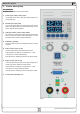
Operating the device
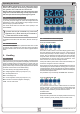
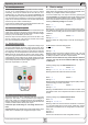
9. Digital interface cards
The device supports following pluggable interface cards:
IF-U1 (USB)
IF-R1 (RS232)
IF-C1 (CAN)
IF-G1 (GPIB/IEEE)
The cards require only a little or no setup after insertion. The card
specicsettingsarekept,evenifthecardisreplacedbyoneof
different type.Thereby it isnot necesary to congure the card
settings everytime a card is inserted.
Details about the technical specs of the interface cards and the
handling, as well as instructions to implement the device into a bus
system or to control the device by means of a PC (LabView etc.)
can be found in the user manual for the IF cards.
Important! Insertion or removal only if the device is completely
switched off (power switch)!
Aboutconguration of the plugged cards see section „Device se
-
tup“.
10. Analogue interface
10.1 General
The integrated, 15 pole analogue interface is located on the front
and offers, amongst others, following possibilities:
• Remote control of current and voltage
• Remote control of voltage, while current = 100%
• Remote control of current, while voltage = 100%
• Remote monitoring of status (OT, OVP, CC, CV)
• Remote monitoring of actual values
• Remotely switching the output on/off
Useful hints:
• Controlling the device with analogue voltages requires to switch
it to remote control with pin „REMOTE“ (5).
• Before connecting the application that is used to control the
power supply, make sure to wire all leads correctly and check if
theapplicationisunabletoinputvoltageshigherthanspecied
(max. 12V).
• The input REM-SB (remote standby, pin 13) overrides the
pushbutton Output On. It means, the output can not be switched
onbythebuttonifthepindenestheoutputstateas„off“.
• The output VREF can be used to build set values for the set value
inputs VSEL and CSEL. For example, if only current control is
required, pin VSEL can be bridged to VREF and CSEL is either
fed by an external voltage (0...5V or 0...10V) or via a potentiometer
between VREF and ground. Also see next section.
• Putting in set values up to 10V while 0...5V range is selected will
ignore any voltage above 5V (clipping) and keep the set value at
100%.
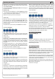
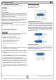
10.2 Example applications
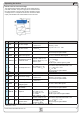
Overview D-Sub socket
Emulated Master-Slave operation
True Master-Slave operation is not possible, because the AI does
not provide set values outputs. But the actual value outputs VMON
and CMON can be used to control the set values inputs VSEL
and CSEL of one or multiple different power supplies of the same
type. Any open set value input can be tied to VREF. In the example
below, the current input of the slave is set to 100% by VREF and
the master only controls the slave voltage with VMON. In a paral-
lel connection, the load current will distribute amongst the power
supplies almost uniformly.
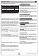
Output off (emergency off)
Pin „REM-SB“ is always operative, so it does not depend on the
remote mode and pin „REMOTE“, even as one of the control inputs
and can thus be used to switch the output off without extra means,
also for an emergency off function.
All the user has to do is to ensure the level of the input is held.