
User manual


11
© 2009, Elektro-Automatik GmbH & Co. KG
EN
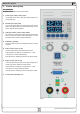
Operating the device
7.5 Overtemperature occurs
Ambient temperatures higher than specied must be avoided!
As soon as an overtemperature (OT) error occurs by internal
overheating, the output is switched off and the LED „OT“ is lit.
Simultaneously, the LED above the pushbutton Output On will
ash,indicatingthattheoutputwillautomaticallyswitchonagainas
soon as the device has cooled down. In case this is not wanted, the
outputcanbemanuallyswitchedoff.ThentheLEDstopsashing
and the output won‘t switch automatically on.
OT errors are recorded as alarm into the internal alarm buffer. This
buffer can be read out via the digital interface.
7.6 Current or voltage is regulated
The output voltage and the resistance of the load determine the
output current. As long as the output current is lower than the ad-
justed current set value, the device will operate in constant voltage
mode (CV). This is indicated by the LED „CV“.
When the output current is limited by the current set value or the
device‘s nominal current, it will change to constant current mode
(CC). This is indicated by the LED „CC“.
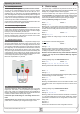
7.7 Remote sense is active
Remote sense operation is used to compensate voltage drops
along the leads between the power supply and the load. Since
this is limited to a certain level, it is strongly advised to match the
cross section of the leads to the output current and thus minimise
the voltage drop. On the frontpanel if the device there is a terminal
Sense where the sense leads are wired to with correct polarity.
The power supply will detect the external sense automatically and
compensate the output voltage by the actual voltage at the load
instead of the output. The output voltage will be raised by the value
of the voltage drop between power supply and load.
Maximum compensation: 1V per lead.
7.8 Mains undervoltage or overvoltage occurs
ThedevicefeaturesanactiverecticationwithPFCandawide
range input. This means, it can be operated at input voltages of
approx. 90V...264V. Input voltages below 90V are considered as
blackout, respectively as complete switch-off and will store the last
condition, as well as switch off the power output.
Permanent input undervoltage or overvoltage must be avo-
ided!
Important! Models with 1500W nominal power will derate the output
power down to 1000W at input voltages below approx.150V.
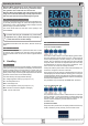
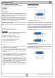
8. Device setup
The device setup is intended to set parameters that are not con-
stantly altered. Two elementary settings are always available, other
settings only if a digital interface card is equipped.
It can be accessed only if the output is off and by pressing the
button Fine/Setup>2s.Alldigitalinterfacespecicsettingsremain
unchanged when inserting a different card. Thereby, the user don‘t
has to setup the interface cards everytime the type changes.
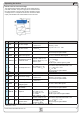
Following elementary settings are available:
Name: P on Default: on
Settings: on, oFF
Meaning: with „on“ the restore of the last condition before switch-
off or blackout is activated. This can used to ensure the device will
continue to work normally, with the last set values, on return from
a blackout.
Name: AI Default: 0-10
Settings: 0-5, 0-10
Meaning: selects the voltage range to use with the analogue in-
terface.
For all interface cards this setting applies:
Name: nodE Default: 1
Settings: 1...30
Meaning: Selects the device‘s address (device node, from the
CAN terminology). When using the device on a bus system (CAN
or GPIB), every device must have a unique address!
Attention! For the GPIB card only select addresses between
1 and 15, even if up to 30 are available! GPIB only supports
15 addresses.
Following settings only with CAN interface IF-C1:
Name: bAUd Default: 100
Settings: 10, 25, 50, 100, 125, 250, 500, 1000
Meaning: Selects the CAN transmission baud rate.
Name: r1d Default: 0
Settings: 0...31
Meaning:Selecttherelocatableidentiersegment(RID).Referto
CAN terminology for further information.
Name: btEr Default: on
Settings: on, off
Meaning: activates/deactives the bus termination resistor of the
CAN interface card. This is required if the device is at the end of
the bus.
Following setting only for RS232 interface IF-R1:
Name: bAUd Default: 576
Settings
: 96, 192, 384, 576
Meaning: Select the serial transmission baudrate in hectobaud.
I.e., 96 means 9600 baud and 576 means 57600 baud. Further
parametersfortheRS232arenotcongurable,butusedasthis:
Parity = odd
Stop bits = 1
Data bits = 8
andhavetobesetsidetothesamecongurationatthePC.